Lexus NX: Reserve Lock Switch
Components
COMPONENTS
ILLUSTRATION
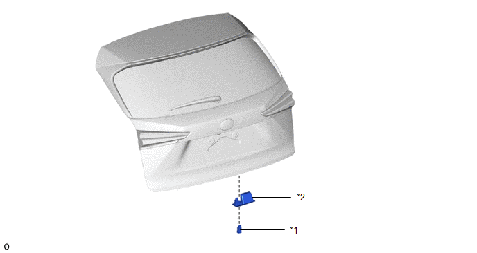
| *1 | DOOR CONTROL SWITCH | *2 | PULL HANDLE |
Removal
REMOVAL
PROCEDURE
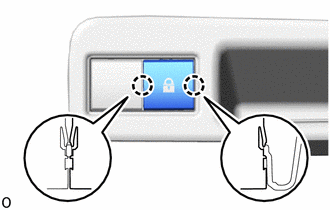
1. REMOVE PULL HANDLE
Click here .gif)
2. REMOVE DOOR CONTROL SWITCH
| (a) Detach the 2 claws and remove the door control switch. |
|
Inspection
INSPECTION
PROCEDURE
1. INSPECT DOOR CONTROL SWITCH
(a) Check the resistance.
| (1) Measure the resistance according to the value(s) in the table below. Standard Resistance:
If the result is not as specified, replace the back door control switch. |
|
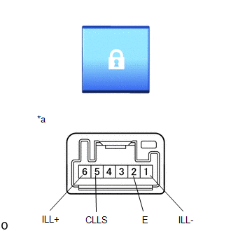
(b) Inspect the illumination operation.
(1) Apply battery voltage to the power back door main switch connector, and check that the back door control switch LED illuminates.
OK:
| Measurement Condition | Specified Condition |
|---|---|
| 6 (ILL+) - Battery positive (+) 1 (ILL-) - Battery negative (-) | LED illuminates |
If the result is not as specified, replace the back door control switch.
Installation
INSTALLATION
PROCEDURE
1. INSTALL DOOR CONTROL SWITCH
(a) Attach the 2 claws to install the door control switch to the pull handle.
2. INSTALL PULL HANDLE
Click here .gif)
READ NEXT:
 Components
COMPONENTS ILLUSTRATION *A w/ Woofer *B w/o Woofer *C w/o Power Back Door *D w/ Power Back Door *1 BACK DOOR CENTER GARNISH *2 BACK DOOR FINISH COVER LH *3 BACK DOO
SEE MORE:
Disposal
DISPOSAL CAUTION / NOTICE / HINT CAUTION: Before performing pre-disposal deployment of any SRS part, review and closely follow all applicable environmental and hazardous material regulations. Pre-disposal deployment may be considered hazardous material treatment. PROCEDURE 1. PRECAUTION CAUTION:
Components
COMPONENTS ILLUSTRATION *1 TONNEAU COVER ASSEMBLY - - ILLUSTRATION *1 DECK BOARD ASSEMBLY *2 DECK FLOOR BOX LH *3 NO. 3 DECK BOARD SUB-ASSEMBLY - - ILLUSTRATION *1 NEGATIVE AUXILIARY BATTERY TERMINAL - - N*m (kgf*cm, ft.*lbf): Specified torque -
