Lexus NX: Relay
On-vehicle Inspection
ON-VEHICLE INSPECTION
PROCEDURE
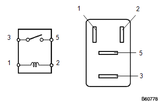
1. INSPECT FRONT WIPER DEICER RELAY
| (a) Measure the resistance according to the value(s) in the table below. Standard Resistance:
If the result is not as specified, replace the front wiper deicer relay. |
|
2. INSPECT DEFOGGER RELAY
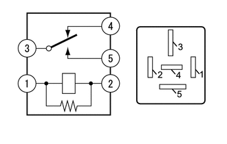
(a) Measure the resistance according to the value(s) in the table below.
Standard Resistance:
| Tester Connection | Condition | Specified Condition |
|---|---|---|
| 3 - 4 | Auxiliary battery voltage is not applied between terminals 1 and 2 | Below 1 Ω |
| Auxiliary battery voltage is applied between terminals 1 and 2 | 10 kΩ or higher | |
| 3 - 5 | Auxiliary battery voltage is not applied between terminals 1 and 2 | 10 kΩ or higher |
| Auxiliary battery voltage is applied between terminals 1 and 2 | Below 1 Ω | |
| 4 - 5 | Always | 10 kΩ or higher |
If the result is not as specified, replace the defogger relay.
READ NEXT:
 Parts Location
PARTS LOCATION ILLUSTRATION *1 AIR CONDITIONING CONTROL ASSEMBLY - REAR WINDOW DEFOGGER SWITCH *2 INSTRUMENT PANEL JUNCTION BLOCK ASSEMBLY - ECU-IG NO.1 FUSE - ECU-IG NO.3 FUSE *3 DLC3
System Diagram
SYSTEM DIAGRAM Communication Table Transmitter Receiver Signal Communication Method Air Conditioning Control Assembly Air Conditioning Amplifier Assembly Rear window defogger switch
SEE MORE:
Components
COMPONENTS ILLUSTRATION *1 COOLER EXPANSION VALVE *2 NO. 1 COOLER EVAPORATOR SUB-ASSEMBLY *3 NO. 1 COOLER THERMISTOR *4 UPPER HEATER CASE *5 LOWER HEATER CASE *6 O-RING N*m (kgf*cm, ft.*lbf): Specified torque ● Non-reusable part Compressor oil ND-OIL
Components
COMPONENTS ILLUSTRATION *1 MAP LIGHT ASSEMBLY (PERSONAL LIGHT) *2 MAP LIGHT SUB-ASSEMBLY
