Lexus NX: Reassembly
REASSEMBLY
CAUTION / NOTICE / HINT
HINT:
Perform "Inspection After Repairs" after replacing the cylinder head sub-assembly.
Click here .gif)
PROCEDURE
1. INSTALL CYLINDER HEAD STUD BOLT
NOTICE:
If a stud bolt is deformed or its threads are damaged, replace it.
| (a) Using an E7 "TORX" socket wrench, install the cylinder head stud bolts. Torque: 9.0 N·m {92 kgf·cm, 80 in·lbf} |
|
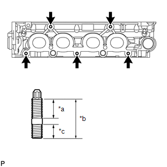
2. INSTALL NO. 1 STRAIGHT SCREW PLUG
NOTICE:
If coolant leaks from a No. 1 straight screw plug or a plug is corroded, replace it.
(a) Using a 10 mm hexagon wrench, install 3 new gaskets and the 3 No. 1 straight screw plugs.
Torque:
44 N·m {449 kgf·cm, 32 ft·lbf}
3. INSTALL NO. 2 STRAIGHT SCREW PLUG
NOTICE:
If coolant leaks from a No. 2 straight screw plug or a plug is corroded, replace it.
(a) Using a 14 mm hexagon wrench, install a new gasket and the No. 2 straight screw plug.
Torque:
78 N·m {795 kgf·cm, 58 ft·lbf}
4. INSTALL VALVE SPRING SEAT
(a) Install the valve spring seats to the cylinder head sub-assembly.
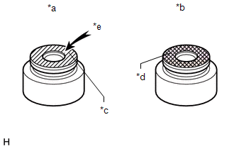
5. INSTALL VALVE STEM OIL SEAL
| (a) Apply a light coat of engine oil to new valve stem oil seals. NOTICE: Pay attention when installing the intake and exhaust valve stem oil seals. For example, installing the intake valve stem oil seal onto the exhaust side or installing the exhaust valve stem oil seal onto the intake side can cause installation problems later. HINT: The intake valve stem oil seals are gray and the exhaust valve stem oil seals are black. |
|
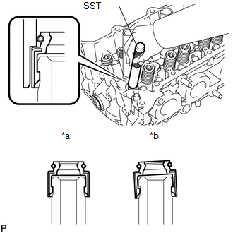
| (b) Using SST, push in the intake and exhaust valve stem oil seals. SST: 09201-41020 NOTICE: Failure to use SST will cause the valve stem oil seal to be damaged or improperly seated. |
|
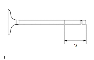
6. INSTALL INTAKE VALVE
| (a) Apply plenty of engine oil to the tip area of the intake valve shown in the illustration. |
|
| (b) Install the intake valve, inner compression spring and valve spring retainer to the cylinder head sub-assembly. NOTICE: Install the same parts in the same combination to their original locations. |
|
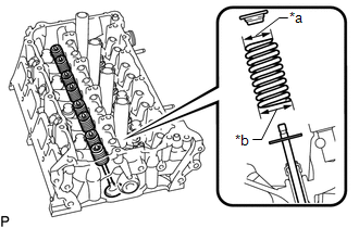
| (c) Using SST and wooden blocks, compress the inner compression spring and install the valve spring retainer locks. SST: 09202-70020 SST: 09202-00021 |
|
.png)
(d) Using a plastic-faced hammer, lightly tap the valve stem tip to ensure a proper fit.
NOTICE:
Be careful not to damage the valve spring retainer.
7. INSTALL EXHAUST VALVE
| (a) Apply plenty of engine oil to the tip area of the exhaust valve shown in the illustration. |
|
| (b) Install the exhaust valve, inner compression spring and valve spring retainer to the cylinder head sub-assembly. NOTICE: Install the same parts in the same combination to their original locations. |
|
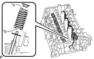
| (c) Using SST and wooden blocks, compress the inner compression spring and install the valve spring retainer locks. SST: 09202-70020 SST: 09202-00021 |
|
.png)
(d) Using a plastic-faced hammer, lightly tap the valve stem tip to ensure a proper fit.
NOTICE:
Be careful not to damage the valve spring retainer.
READ NEXT:
 Repair
REPAIR PROCEDURE 1. REPAIR INTAKE VALVE SEAT NOTICE:
Repair the seat while checking the seating position.
Keep the lip free of foreign matter.
Take off the cutter gradually to make the intake v
Components
COMPONENTS ILLUSTRATION *1 EGR COOLER ASSEMBLY *2 EGR VALVE ASSEMBLY *3 FUEL DELIVERY PIPE *4 INJECTOR VIBRATION INSULATOR *5 INTAKE MANIFOLD *6 NO. 1 EGR PIPE *7 N
SEE MORE:
Front Right Sensor Malfunction (C1AE4)
DESCRIPTION The front corner ultrasonic sensor (FR sensor) is installed to the front bumper. The clearance warning ECU assembly detects obstacles based on signals received from the front corner ultrasonic sensor (FR sensor). If the front corner ultrasonic sensor (FR sensor) has an open circuit or ot
Random Access Memory (RAM) (P0604)
MONITOR DESCRIPTION The ECM continuously monitors its internal memory status. This self-check ensures that the ECM is functioning properly. The ECM memory status is diagnosed by internal mirroring of the main CPU and sub CPU to detect Random Access Memory (RAM) errors. If outputs from these CPUs are
