Lexus NX: Repair
REPAIR
PROCEDURE
1. REPAIR INTAKE VALVE SEAT
NOTICE:
- Repair the seat while checking the seating position.
- Keep the lip free of foreign matter.
- Take off the cutter gradually to make the intake valve seat smooth.
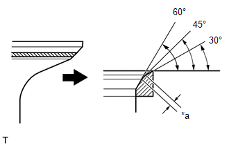
| (a) Using a 45° cutter, resurface the valve seat so that the valve seat width is more than the specification. |
|
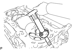
| (b) Using 30° and 60° cutters, correct the valve seat so that the valve contacts the entire circumference of the seat. The contact should be in the center of the valve seat, and the valve seat width should be maintained within the specified range around the entire circumference of the seat. Standard width: 1.0 to 1.4 mm (0.0394 to 0.0551 in.) |
|
(c) Hand-lap the valve and valve seat with an abrasive compound.
(d) Check the valve seating position.
2. REPAIR EXHAUST VALVE SEAT
NOTICE:
- Repair the seat while checking the seating position.
- Keep the lip free of foreign matter.
- Take off the cutter gradually to make the exhaust valve seat smooth.
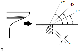
| (a) Using a 45° cutter, resurface the valve seat so that the valve seat width is more than the specification. |
|
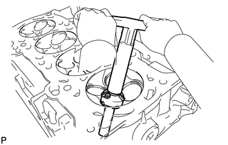
| (b) Using 30° and 75° cutters, correct the valve seat so that the valve contacts the entire circumference of the seat. The contact should be in the center of the valve seat, and the valve seat width should be maintained within the specified range around the entire circumference of the seat. Standard width: 1.2 to 1.6 mm (0.0472 to 0.0630 in.) |
|
(c) Hand-lap the valve and valve seat with an abrasive compound.
(d) Check the valve seating position.
READ NEXT:
 Components
COMPONENTS ILLUSTRATION *1 EGR COOLER ASSEMBLY *2 EGR VALVE ASSEMBLY *3 FUEL DELIVERY PIPE *4 INJECTOR VIBRATION INSULATOR *5 INTAKE MANIFOLD *6 NO. 1 EGR PIPE *7 N
Removal
REMOVAL PROCEDURE 1. REMOVE TIMING CHAIN COVER ASSEMBLY Click here 2. REMOVE EXHAUST MANIFOLD CONVERTER SUB-ASSEMBLY Click here 3. REMOVE THROTTLE WITH MOTOR BODY ASSEMBLY Click here 4. REMOVE W
SEE MORE:
Vehicle Speed Signal (C1541)
DESCRIPTION The power steering ECU assembly receives vehicle speed signals from the skid control ECU (brake booster with master cylinder assembly) via CAN communication. The ECU provides appropriate assisting force in accordance with the vehicle speed based on the signals. DTC No. Detection Ite
Dtc Check / Clear
DTC CHECK / CLEAR DTC CHECK (a) Connect the Techstream to the DLC3. (b) Turn the power switch on (IG). (c) Turn the Techstream on. (d) Enter the following menus: Body Electrical / Vehicle Proximity Notification System / Trouble Codes. Body Electrical > Vehicle Proximity Notification System > T
