Lexus NX: Reassembly
REASSEMBLY
PROCEDURE
1. INSTALL NO. 2 STEERING RACK BOOT
| (a) Apply lithium soap base glycol grease to the inside of the steering rack end. |
|
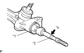
(b) Install the No. 2 steering rack boot to the groove on the rack housing.
NOTICE:
- Make sure that the boot is free of rust and foreign matter.
- Be careful not to damage or twist the boot.
2. INSTALL NO. 1 STEERING RACK BOOT
HINT:
Use the same procedure as for the No. 2 steering rack boot.
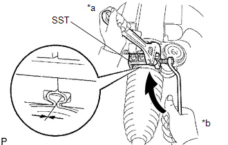
3. TIGHTEN NO. 2 STEERING RACK BOOT CLAMP
| (a) Using SST, tighten a new No. 2 steering rack boot clamp as shown in the illustration. SST: 09521-24010 Clearance: 3.0 mm (0.118 in.) or less NOTICE: Be careful not to damage or twist the boot. |
|
4. TIGHTEN NO. 1 STEERING RACK BOOT CLAMP
HINT:
Use the same procedure as for the No. 2 steering rack boot clamp.
5. INSTALL STEERING RACK BOOT CLIP
(a) Using pliers, install the 2 steering rack boot clips.
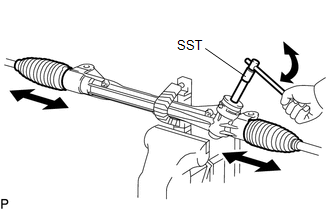
6. INSPECT STEERING GEAR ASSEMBLY
| (a) Using SST, rotate the pinion shaft to see if both the left and right steering rack boots expand and contract smoothly. SST: 09616-00011 HINT: If the result is not as specified, use new steering rack boot clamps and reinstall the steering rack boots. |
|
7. CONNECT TIE ROD END SUB-ASSEMBLY LH
| (a) Install the lock nut and tie rod end sub-assembly LH to the steering gear assembly so that the matchmarks align. HINT: After adjusting toe-in, tighten the lock nuts to the specified torque. |
|
8. CONNECT TIE ROD END SUB-ASSEMBLY RH
HINT:
Use the same procedure described for the LH side.
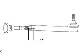
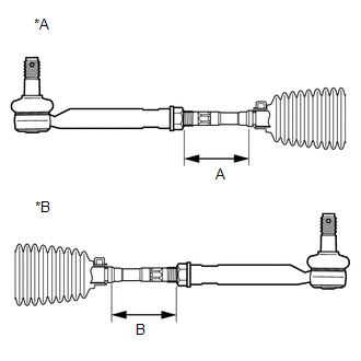
9. CHECK TIE ROD END SUB-ASSEMBLY
| (a) Adjust the tie rod end sub-assembly LH and RH so that distance A and distance B are within the specified ranges. Reference Values:
HINT:
|
|
READ NEXT:
 Installation
INSTALLATION PROCEDURE 1. INSTALL STEERING GEAR ASSEMBLY (a) Install the steering gear assembly to the front suspension crossmember with the 2 bolts and 2 nuts. Torque: 110 N·m {1122 kgf·cm, 81 ftÂ
SEE MORE:
Generator Control Module (P0A1A-517,P0A1A-809)
DTC SUMMARY MALFUNCTION DESCRIPTION These DTCs indicate that a large current flowed in the inverter for the generator. The cause of this malfunction may be one of the following: Internal inverter malfunction
Internal circuit malfunction in the inverter for the generator
Malfunction in ECU that
Maintenance and care
Maintenance and care
Cleaning and protecting the vehicle
exterior
Perform cleaning in a manner
appropriate to each component
and its material.
Cleaning instructions
Working from top to bottom, liberally
apply water to the vehicle body,
wheel wells and underside of the
vehicle to remo
