Lexus NX: Removal
REMOVAL
PROCEDURE
1. REMOVE CONSOLE ARMREST ASSEMBLY
Click here .gif)
2. REMOVE UPPER NO. 2 CONSOLE PANEL GARNISH
Click here
3. REMOVE INSTRUMENT SIDE PANEL LH
Click here
4. REMOVE NO. 1 INSTRUMENT PANEL SAFETY PAD SUB-ASSEMBLY
Click here
5. REMOVE NO. 1 INSTRUMENT PANEL UNDER COVER SUB-ASSEMBLY
Click here
6. REMOVE LOWER NO. 1 INSTRUMENT PANEL FINISH PANEL
Click here
7. REMOVE NO. 1 SWITCH HOLE BASE
Click here
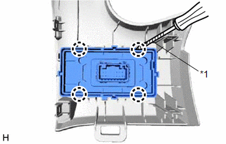
8. REMOVE HEADUP DISPLAY SWITCH ASSEMBLY
| (a) Using a screwdriver, detach the 4 claws and remove the headup display switch assembly. HINT: Tape the screwdriver tip before use. |
|
READ NEXT:
 Inspection
INSPECTION PROCEDURE 1. INSPECT HEADUP DISPLAY SWITCH ASSEMBLY *1 HUD Switch *2 TILT Switch *3 RHEOSTAT Switch *4 DISP Switch *a Component without harness connected (Head
Installation
INSTALLATION PROCEDURE 1. INSTALL HEADUP DISPLAY SWITCH ASSEMBLY (a) Attach the 4 claws to install the headup display switch assembly. 2. INSTALL NO. 1 SWITCH HOLE BASE Click here 3
SEE MORE:
Oil Pressure Switch
ComponentsCOMPONENTS ILLUSTRATION *1 ENGINE OIL PRESSURE SWITCH ASSEMBLY - - N*m (kgf*cm, ft.*lbf): Specified torque TOYOTA Genuine Adhesive 1344, Three Bond 1344 or equivalent. ★ Precoated part - - RemovalREMOVAL PROCEDURE 1. REMOVE ENGINE OIL PRESSURE SWITCH
Installation
INSTALLATION CAUTION / NOTICE / HINT HINT:
Use the same procedure for the RH and LH sides.
The procedures listed below are for the LH side.
PROCEDURE 1. INSTALL FRONT DOOR LOWER OUTSIDE MOULDING SUB-ASSEMBLY LH HINT: When installing the front door lower outside moulding sub-assembly LH, heat
© 2016-2026 Copyright www.lexunx.com
