Lexus NX: Relay
On-vehicle Inspection
ON-VEHICLE INSPECTION
PROCEDURE
1. INSPECT JUNCTION BLOCK
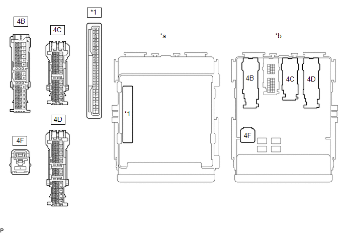
| *1 | Main Body ECU | - | - |
| *a | Component without harness connected (Junction Block) | *b | Component without main body ECU connected (Junction Block) |
NOTICE:
Before performing the relay inspections for the relays of the junction block, inspect the ECU-IG NO. 2, ECU-IG NO. 4 and ECU-IG NO. 5 fuses.
(a) Inspect the IG1 NO. 1 relay.
(1) Measure the resistance according to the value(s) in the table below.
Standard Resistance:
| Tester Connection | Condition | Specified Condition |
|---|---|---|
| 4F-1 - 4C-21 | Battery voltage not applied to terminals 4B-46 and -4D-28 | 10 kΩ or higher |
| Battery voltage applied to terminals 4B-46 and 4D-28 | Below 1 Ω |
If the result is not as specified, replace the junction block.
(b) Inspect the IG1 NO. 2 relay.
(1) Measure the resistance according to the value(s) in the table below.
Standard Resistance:
| Tester Connection | Condition | Specified Condition |
|---|---|---|
| 4F-1 - 4C-41 | Battery voltage not applied to terminals 4B-46 and -4D-28 | 10 kΩ or higher |
| Battery voltage applied to terminals 4B-46 and 4D-28 | Below 1 Ω |
If the result is not as specified, replace the junction block.
(c) Inspect the IG1 NO. 3 relay.
(1) Measure the resistance according to the value(s) in the table below.
Standard Resistance:
| Tester Connection | Condition | Specified Condition |
|---|---|---|
| 4F-1 - 4D-34 | Battery voltage not applied to terminals 4B-46 and -4D-28 | 10 kΩ or higher |
| Battery voltage applied to terminals 4B-46 and 4D-28 | Below 1 Ω |
If the result is not as specified, replace the junction block.
2. INSPECT EFI MAIN RELAY (EFI MAIN)
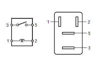
(a) Measure the resistance according to the value(s) in the table below.
Standard Resistance:
| Tester Connection | Condition | Specified Condition |
|---|---|---|
| 3 - 5 | Battery voltage not applied to terminals 1 and 2 | 10 kΩ or higher |
| Battery voltage applied to terminals 1 and 2 | Below 1 Ω |
If the result is not as specified, replace the EFI main relay.
3. INSPECT EFI MAIN NO. 2 RELAY (EFI MAIN NO. 2)
(a) Measure the resistance according to the value(s) in the table below.
Standard Resistance:
| Tester Connection | Condition | Specified Condition |
|---|---|---|
| 3 - 5 | Battery voltage not applied to terminals 1 and 2 | 10 kΩ or higher |
| Battery voltage applied to terminals 1 and 2 | Below 1 Ω |
If the result is not as specified, replace the EFI main No. 2 relay.
4. INSPECT IGNITION NO. 2 MAIN RELAY (IG2-MAIN)
(a) Measure the resistance according to the value(s) in the table below.
Standard Resistance:
| Tester Connection | Condition | Specified Condition |
|---|---|---|
| 3 - 5 | Battery voltage not applied to terminals 1 and 2 | 10 kΩ or higher |
| Battery voltage applied to terminals 1 and 2 | Below 1 Ω |
If the result is not as specified, replace the ignition No. 2 main relay.
READ NEXT:
 Precaution
PRECAUTION INITIALIZATION NOTICE: Perform Registration (VIN registration) when replacing the ECM. Click here DISCONNECT CABLE FROM NEGATIVE AUXILIARY BATTERY TERMINAL NOTICE:
After the power swit
Definition Of Terms
DEFINITION OF TERMS Term Definition Monitor Description Description of what the ECM monitors and how it detects malfunctions (monitoring purpose and details). Related DTCs Group of di
SEE MORE:
Short in P/T Squib (RH) Circuit (B1900-B1903)
DESCRIPTION The front pretensioner RH circuit consists of the airbag ECU assembly and front seat outer belt assembly RH. This circuit instructs the SRS to deploy when deployment conditions are met. These DTCs are stored when a malfunction is detected in the front pretensioner RH circuit. DTC No.
Removal
REMOVAL CAUTION / NOTICE / HINT CAUTION: Wear protective gloves. Sharp areas on the parts may injure your hands. HINT:
Use the same procedure for the RH and LH sides.
The procedure listed below is for the LH side.
PROCEDURE 1. REMOVE FRONT SEAT ASSEMBLY LH Click here 2. REMOVE FRONT LOWER
