Lexus NX: Relay
On-vehicle Inspection
ON-VEHICLE INSPECTION
PROCEDURE
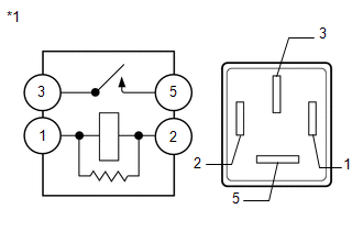
1. INSPECT IGNITION CONTROL RELAY (IGCT)
| (a) Measure the resistance according to the value(s) in the table below. Standard Resistance:
If the result is not as specified, replace the ignition control relay. |
|
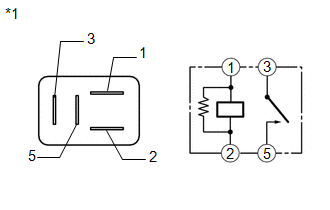
2. INSPECT HYBRID WATER PUMP RELAY (INV W/PMP)
| (a) Measure the resistance according to the value(s) in the table below. Standard Resistance:
If the result is not as specified, replace the hybrid water pump relay. |
|
READ NEXT:
 Components
COMPONENTS ILLUSTRATION *1 DECK FLOOR BOX LH *2 NO. 3 DECK BOARD SUB-ASSEMBLY *3 REAR DECK FLOOR BOX *4 NEGATIVE AUXILIARY BATTERY TERMINAL N*m (kgf*cm, ft.*lbf): Specified
Removal
REMOVAL PROCEDURE 1. PRECAUTION CAUTION: The hybrid system has high-voltage circuits. Accidents, such as electric shock, or electric leaks may result if the hybrid system is not operated in a correct
SEE MORE:
Removal
REMOVAL PROCEDURE 1. REMOVE INSTRUMENT PANEL FINISH PLATE 2. REMOVE MULTI-DISPLAY ASSEMBLY WITH BRACKET Click here 3. REMOVE CONSOLE ARMREST ASSEMBLY Click here 4. REMOVE UPPER REAR CONSOLE PANEL Click here 5. REMOVE UPPER NO. 1 CONSOLE PANEL GARNISH Click here 6. REMOVE UPPER NO. 2 CONS
ECM / PCM Processor (P0606)
MONITOR DESCRIPTION The ECM continuously monitors its main and sub CPUs. This self-check ensures that the ECM is functioning properly. If outputs from these CPUs are different and deviate from the standard, the ECM will illuminate the MIL and store this DTC. DTC No. Detection Item DTC Detecti
