Lexus NX: Removal
REMOVAL
PROCEDURE
1. PRECAUTION
CAUTION:
The hybrid system has high-voltage circuits. Accidents, such as electric shock, or electric leaks may result if the hybrid system is not operated in a correct manner. Make sure to follow the correct procedure.
Click here .gif)
NOTICE:
After turning the power switch is turned off, there may be a waiting time before disconnecting the auxiliary negative (-) battery terminal.
Click here
2. REMOVE NO. 3 DECK BOARD SUB-ASSEMBLY
Click here
3. REMOVE REAR DECK FLOOR BOX
Click here
4. REMOVE DECK FLOOR BOX LH
Click here
5. DISCONNECT CABLE FROM NEGATIVE AUXILIARY BATTERY TERMINAL
(a) Loosen the nut and disconnect the cable from the negative (-) auxiliary battery terminal.
6. REMOVE BATTERY SERVICE HOLE COVER
(a) Detach the 4 claws and remove the battery service hole cover.
HINT:
Detach the upper 2 claws and then pull them up to remove.
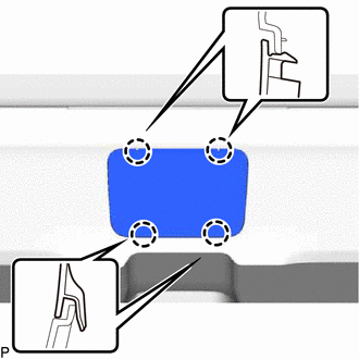
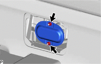
7. REMOVE HYBRID BATTERY SERVICE PLUG COVER
CAUTION:
Wear insulated gloves and use insulated tools.
| (a) Using an insulated tool, remove the 2 nuts and hybrid battery service plug cover. |
|
8. REMOVE SERVICE PLUG GRIP
CAUTION:
- Be sure to wear insulated gloves.
- Remove the service plug grip to interrupt the high voltage circuit at the time of inspection or repair.
- Keep the removed service plug grip in your pocket to prevent other technicians from accidentally reconnecting it while you are servicing the vehicle.
- All the high voltage wiring connectors are orange.
NOTICE:
After removing the service plug grip, turning the power switch on (READY) may cause a malfunction. Do not turn the power switch on (READY) unless instructed by the repair manual.
HINT:
Waiting for at least 10 minutes is required to discharge the high voltage capacitor inside the inverter with converter assembly.
(a) Wear insulated gloves and remove the service plug grip after sliding up the lever of the service plug grip as shown in the illustration.
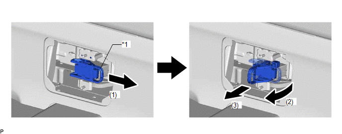
| *1 | Service Plug Grip Lever | - | - |
(1) Slide the lever to release the lock.
(2) Lift the lever straight up.
NOTICE:
Do not exert excessive force to lift up the lever.
(3) Pull the service plug grip out from the HV battery to remove it.
READ NEXT:
 Inspection
INSPECTION PROCEDURE 1. INSPECT SERVICE PLUG GRIP (a) Measure the resistance according to the value(s) in the table below. Standard Resistance: Tester Connection Condition Specified Conditi
Installation
INSTALLATION PROCEDURE 1. INSTALL SERVICE PLUG GRIP CAUTION: Wear insulating gloves. NOTICE: Before connecting the service plug, check that no parts and tools remain and that the high voltage terminal
Sub Radiator
RemovalREMOVAL PROCEDURE 1. REMOVE NO. 1 ENGINE UNDER COVER ASSEMBLY Click here 2. DRAIN COOLANT (for Inverter Coolant) Click here 3. REMOVE UPPER RADIATOR SUPPORT SUB-ASSEMBLY Click here 4.
SEE MORE:
Rear Door Courtesy Switch
ComponentsCOMPONENTS ILLUSTRATION *1 REAR DOOR COURTESY LIGHT SWITCH ASSEMBLY - - N*m (kgf*cm, ft.*lbf): Specified torque - - RemovalREMOVAL CAUTION / NOTICE / HINT HINT:
Use the same procedure for the RH and LH sides.
The procedure listed below is for the LH side.
Open in Bus 3 Main Bus Line
DESCRIPTION There may be an open circuit in one of the CAN main bus lines when the resistance between terminals 6 (CA3H) and 21 (CA3L) of the central gateway ECU (network gateway ECU) is 70 Ω or higher. Symptom Trouble Area
Resistance between terminals 6 (CA3H) and 21 (CA3L) of the cent
