Lexus NX: Air Outlet Damper Control Servo Motor Circuit (Rear) (B1449)
DESCRIPTION
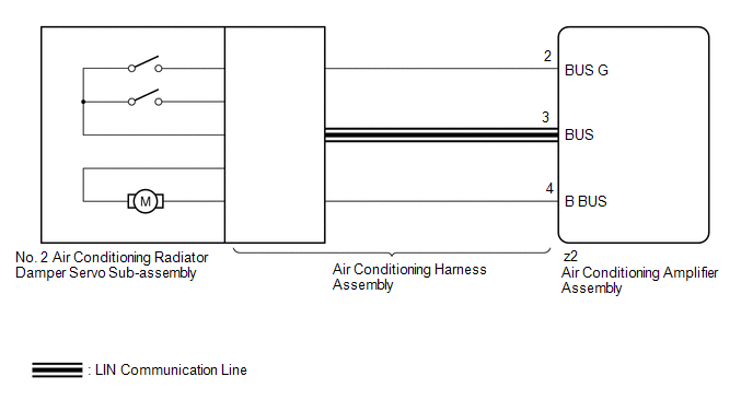
The No. 2 air conditioning radiator damper servo sub-assembly sends pulse signals to inform the air conditioning amplifier assembly of the damper position. The air conditioning amplifier assembly activates the motor (normal or reverse) based on these signals to move the No. 2 air conditioning radiator damper servo sub-assembly to the appropriate position, which controls the rear air outlet switching.
| DTC No. | Detection Item | DTC Detection Condition | Trouble Area | Memory | Note |
|---|---|---|---|---|---|
| B1449 | Air Outlet Damper Control Servo Motor Circuit (Rear) | Rear air outlet damper position sensor value does not change even if air conditioning amplifier assembly operates No. 2 air conditioning radiator damper servo sub-assembly |
| Memorized (30 seconds or more)* | - |
- *: The air conditioning amplifier assembly stores this DTC if the malfunction has occurred for the period of time indicated in the brackets.
WIRING DIAGRAM
CAUTION / NOTICE / HINT
NOTICE:
When the auxiliary battery is disconnected or the air conditioning amplifier assembly is replaced, be sure to perform servo motor initialization.
Click here .gif)
HINT:
Confirm that no mechanical problem is present because this DTC can be output when either a damper link or damper is mechanically locked.
PROCEDURE
| 1. | CHECK FOR DTC |
(a) Clear the DTC.
Click here
(b) Check for DTC.
Click here
| Result | Proceed to |
|---|---|
| DTC B1449 is not output | A |
| DTC B1449 is output | B |
| DTC B1449 and B1497 are output | C |
| A | .gif) | USE SIMULATION METHOD TO CHECK |
| C | | GO TO DTC B1497 |
|
.gif)
| 2. | READ VALUE USING TECHSTREAM |
(a) Connect the Techstream to the DLC3.
(b) Turn the power switch on (IG).
(c) Turn the Techstream on.
(d) Operate the mode switch.
(e) Enter the following menus: Body Electrical / Air Conditioner / Data List.
(f) Check the value(s) by referring to the table below.
Body Electrical > Air Conditioner > Data List| Tester Display | Measurement Item | Range | Normal Condition | Diagnostic Note |
|---|---|---|---|---|
| Air Outlet Servo Pulse (R) | No. 2 air conditioning radiator damper servo sub-assembly target pulse | Min.: 128 Max.: 383 | FACE: 264 (pulse) B/L: 245 (pulse) FOOT: 208 (pulse) Foot/DEF: 208 (pulse) SHUT: 166 (pulse) | - |
| Air Outlet Servo Actual Pls(R) | No. 2 air conditioning radiator damper servo sub-assembly actual pulse | Min.: 128 Max.: 383 | FACE: 264 (pulse) B/L: 245 (pulse) FOOT: 208 (pulse) Foot/DEF: 208 (pulse) SHUT: 166 (pulse) | - |
| Tester Display |
|---|
| Air Outlet Servo Pulse (R) |
| Air Outlet Servo Actual Pls(R) |
OK:
When the mode switch is operated, the actual pulse changes following the target pulse.
| Result | Proceed to |
|---|---|
| Target pulse and actual pulse do not change | A |
| Target pulse changes but actual pulse does not change | B |
| Actual pulse changes following the target pulse (When troubleshooting according to the DTC) | C |
| Actual pulse changes following the target pulse (When troubleshooting according to Problem Symptoms Table) | D |
| A | | REPLACE AIR CONDITIONING AMPLIFIER ASSEMBLY |
| C | | GO TO STEP 5 |
| D | | PROCEED TO NEXT SUSPECTED AREA SHOWN IN PROBLEM SYMPTOMS TABLE |
|
| 3. | CHECK NO. 2 AIR CONDITIONING RADIATOR DAMPER SERVO SUB-ASSEMBLY |
(a) Replace the No. 2 air conditioning radiator damper servo sub-assembly.
Click here
HINT:
Since the servo motor cannot be inspected while it is removed from the vehicle, replace the servo motor with a new or known good one and check that the condition returns to normal.
(b) Clear the DTC.
Click here
(c) Check for DTCs.
Click here
| Result | Proceed to |
|---|---|
| DTC B1449 is not output | A |
| DTC B1449 is output | B |
| A | | END (NO. 2 AIR CONDITIONING RADIATOR DAMPER SERVO SUB-ASSEMBLY IS DEFECTIVE) |
|
| 4. | CHECK AIR CONDITIONING HARNESS ASSEMBLY |
(a) Replace the air conditioning harness assembly.
Click here
HINT:
Since the air conditioning harness assembly cannot be inspected while it is removed from the vehicle, replace the air conditioning harness assembly with a new or known good one and check that the condition returns to normal.
(b) Clear the DTC.
Click here
(c) Check for DTCs.
Click here
| Result | Proceed to |
|---|---|
| DTC B1449 is not output | A |
| DTC B1449 is output | B |
| A | | END (AIR CONDITIONING HARNESS ASSEMBLY IS DEFECTIVE) |
| B | | REPLACE AIR CONDITIONING AMPLIFIER ASSEMBLY |
| 5. | CHECK FOR DTC |
(a) Clear the DTC.
Click here
(b) Check for DTC.
Click here
| Result | Proceed to |
|---|---|
| DTC B1449 is not output | A |
| DTC B1449 is output | B |
| A | | USE SIMULATION METHOD TO CHECK |
| B | | REPLACE AIR CONDITIONING AMPLIFIER ASSEMBLY |
READ NEXT:
 A/C Inverter High Voltage Power Resource System Malfunction (B1471)
DESCRIPTION The hybrid vehicle control ECU monitors the voltage of the HV battery. The hybrid vehicle control ECU stops compressor control and stores this DTC when the monitored voltage is outside the
A/C Inverter High Voltage Output System Malfunction (B1472)
DESCRIPTION The inverter in the compressor with motor assembly outputs high-voltage to operate the motor. If there is an open or short in the output circuit, the hybrid vehicle control ECU will stop c
A/C Inverter Start-up Signal System Malfunction (B1473)
DESCRIPTION The inverter activation signal is sent to the compressor with motor assembly from the hybrid vehicle control ECU. Compressor control is stopped and this DTC is stored if there is an open o
SEE MORE:
DCM System Internal Failure (B15A804)
DESCRIPTION This DTC is stored when an internal circuit malfunction is detected by the DCM (telematics transceiver) self check. DTC No. Detection Item DTC Detection Condition Trouble Area B15A804 DCM System Internal Failure DCM (telematics transceiver) internal malfunction DCM (te
Precaution
PRECAUTION PRECAUTION FOR DISCONNECTING CABLE FROM NEGATIVE AUXILIARY BATTERY TERMINAL NOTICE: When disconnecting the cable from the negative (-) auxiliary battery terminal, perform steering angle sensor zero point calibration after the cable is reconnected. Click here PRECAUTIONS FOR LANE TRACING
