Lexus NX: Components
COMPONENTS
ILLUSTRATION
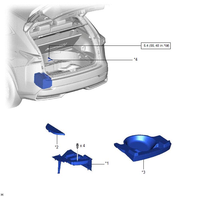
| *1 | DECK FLOOR BOX LH | *2 | NO. 3 DECK BOARD SUB-ASSEMBLY |
| *3 | REAR DECK FLOOR BOX | *4 | NEGATIVE AUXILIARY BATTERY TERMINAL |
.png) | N*m (kgf*cm, ft.*lbf): Specified torque | - | - |
ILLUSTRATION
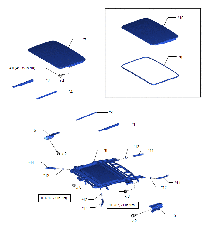
| *1 | NO. 1 SLIDING ROOF SIDE GARNISH LH | *2 | NO. 1 SLIDING ROOF SIDE GARNISH RH |
| *3 | NO. 2 SLIDING ROOF SIDE GARNISH LH | *4 | NO. 2 SLIDING ROOF SIDE GARNISH RH |
| *5 | REAR SIDE RAIL SPACER LH | *6 | REAR SIDE RAIL SPACER RH |
| *7 | SLIDING ROOF GLASS SUB-ASSEMBLY | *8 | SLIDING ROOF HOUSING SUB-ASSEMBLY |
| *9 | SLIDING ROOF WEATHERSTRIP | *10 | SLIDING ROOF PANEL SUB-ASSEMBLY |
| *11 | SLIDING ROOF DRAIN HOSE | *12 | SLIDING ROOF DRAIN HOSE CLAMP |
| | N*m (kgf*cm, ft.*lbf): Specified torque | - | - |
ILLUSTRATION
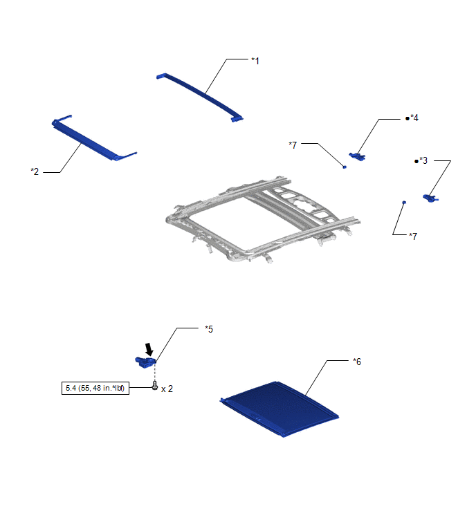
| *1 | REAR ROOF DRIP CHANNEL | *2 | ROOF WIND DEFLECTOR PANEL SUB-ASSEMBLY |
| *3 | SLIDE ROOF DRAIN HOSE JOINT LH | *4 | SLIDE ROOF DRAIN HOSE JOINT RH |
| *5 | SLIDING ROOF DRIVE GEAR SUB-ASSEMBLY | *6 | SUNSHADE TRIM SUB-ASSEMBLY |
| *7 | SLIDING ROOF SUNSHADE STOPPER | - | - |
| | N*m (kgf*cm, ft.*lbf): Specified torque | ● | Non-reusable part |
.png) | MP grease | - | - |
READ NEXT:
 Removal
REMOVAL PROCEDURE 1. PRECAUTION NOTICE: After the power switch is turned off, there may be a waiting time before disconnecting the negative (-) auxiliary battery terminal. Click here 2. REMOVE NO. 3
Reassembly
REASSEMBLY PROCEDURE 1. INSTALL ROOF WIND DEFLECTOR PANEL SUB-ASSEMBLY (a) Attach the 2 guides as shown in the illustration to install the roof wind deflector panel sub-assembly. (b) Attach the 2 spr
Installation
INSTALLATION PROCEDURE 1. INSTALL SLIDING ROOF HOUSING SUB-ASSEMBLY (a) Temporarily install the sliding roof housing sub-assembly with the 8 bolts and 8 nuts. (b) Tighten the nuts in the order indica
SEE MORE:
How To Proceed With Troubleshooting
CAUTION / NOTICE / HINT HINT:
Use the following procedure to troubleshoot the blind spot monitor system.
*: Use the Techstream.
PROCEDURE 1. VEHICLE BROUGHT TO WORKSHOP
NEXT 2. CUSTOMER PROBLEM ANALYSIS
NEXT 3. INSPECT AUXILIARY BATTE
How To Proceed With Troubleshooting
CAUTION / NOTICE / HINT HINT:
Use this procedure to troubleshoot the immobiliser system.
*: Use the Techstream.
PROCEDURE 1. VEHICLE BROUGHT TO WORKSHOP
NEXT 2. CUSTOMER PROBLEM ANALYSIS HINT:
In troubleshooting, confirm that the problem symptoms have be
