Lexus NX: Relay
On-vehicle Inspection
ON-VEHICLE INSPECTION
PROCEDURE
1. INSPECT LIGHT CUT RELAY
(a) Remove the upper instrument panel sub-assembly.
Click here .gif)
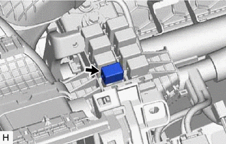
| (b) Remove the light cut relay. |
|
| (c) Check the resistance. (1) Measure the resistance according to the value(s) in the table below. Standard Resistance:
If the result is not as specified, replace the light cut relay. |
|

(d) Install the light cut relay.
(e) Install the upper instrument panel sub-assembly.
Click here
READ NEXT:
 Room Light
ComponentsCOMPONENTS ILLUSTRATION *A for Normal Roof *B for Sliding Roof *C for Glass Roof - - *1 SPOT LIGHT ASSEMBLY (ROOM LIGHT) - - RemovalREMOVAL PROCEDURE 1. RE
Vanity Light
ComponentsCOMPONENTS ILLUSTRATION *1 VANITY LIGHT ASSEMBLY *2 VANITY LIGHT BULB *3 VANITY LIGHT HOLDER - - RemovalREMOVAL CAUTION / NOTICE / HINT HINT:
Use the same procedu
Vanity Light Bulb
ReplacementREPLACEMENT CAUTION / NOTICE / HINT HINT:
Use the same procedure for the RH and LH sides.
The procedure listed below is for the LH side.
PROCEDURE 1. DISCONNECT VANITY LIGHT ASSEMB
SEE MORE:
Inspection
INSPECTION PROCEDURE 1. INSPECT CYLINDER BLOCK FOR WARPAGE (a) Using a precision straightedge and feeler gauge, measure the warpage of the surface that contacts the cylinder head gasket. Maximum warpage: 0.05 mm (0.00197 in.) If the warpage is more than the maximum, replace the cylinder block.
Mirror Heater does not Operate with Rear Defogger Switch
DESCRIPTION When the rear window defogger switch (mirror heater switch) on the air conditioning control assembly is pressed, the operation signal is transmitted to the air conditioning amplifier assembly via LIN communication. When the air conditioning amplifier assembly receives the signal, it turn
© 2016-2026 Copyright www.lexunx.com
