Lexus NX: Vanity Light
Components
COMPONENTS
ILLUSTRATION
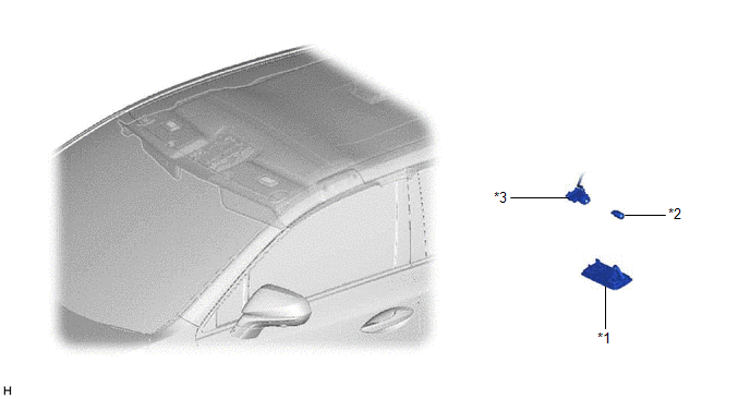
| *1 | VANITY LIGHT ASSEMBLY | *2 | VANITY LIGHT BULB |
| *3 | VANITY LIGHT HOLDER | - | - |
Removal
REMOVAL
CAUTION / NOTICE / HINT
HINT:
- Use the same procedure for the RH and LH sides.
- The procedure listed below is for the LH side.
PROCEDURE
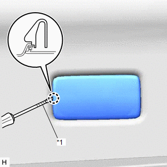
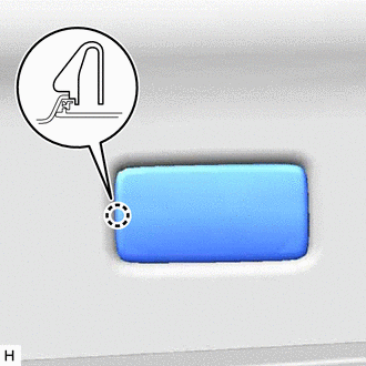
1. REMOVE VANITY LIGHT ASSEMBLY
| (a) Using a screwdriver, detach the claw and remove the vanity light assembly. HINT: Tape the screwdriver tip before use. |
|
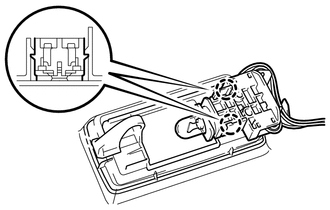
| (b) Detach the 2 claws and remove the vanity light holder. |
|
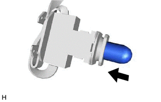
2. REMOVE VANITY LIGHT BULB
| (a) Remove the vanity light bulb from the vanity light holder. |
|

Installation
INSTALLATION
CAUTION / NOTICE / HINT
HINT:
- Use the same procedure for the RH and LH sides.
- The procedure listed below is for the LH side.
PROCEDURE
1. INSTALL VANITY LIGHT BULB
| (a) Install the vanity light bulb to the vanity light holder. |
|
2. INSTALL VANITY LIGHT ASSEMBLY
| (a) Attach the 2 claws to install the vanity light holder. |
|
.png)
| (b) Attach the claw to install the vanity light assembly. |
|
READ NEXT:
 Vanity Light Bulb
ReplacementREPLACEMENT CAUTION / NOTICE / HINT HINT:
Use the same procedure for the RH and LH sides.
The procedure listed below is for the LH side.
PROCEDURE 1. DISCONNECT VANITY LIGHT ASSEMB
SEE MORE:
Park / Neutral Position Switch Circuit
DESCRIPTION The fold seat control ECU receives switch operation signals, back door open/close signal*1, rear door open/close signal*2 and driving condition signal (shift position, stop light switch assembly, parking brake switch assembly signals) from the main body ECU (multiplex network body ECU).
Pcv Valve
ComponentsCOMPONENTS ILLUSTRATION *1 PCV VALVE SUB-ASSEMBLY *2 NO. 2 PCV HOSE N*m (kgf*cm, ft.*lbf): Specified torque Toyota Genuine Adhesive 1324, Three Bond 1324 or equivalent ★ Precoated part - - RemovalREMOVAL PROCEDURE 1. REMOVE INTAKE MANIFOLD Click here
