Lexus NX: Room Light
Components
COMPONENTS
ILLUSTRATION
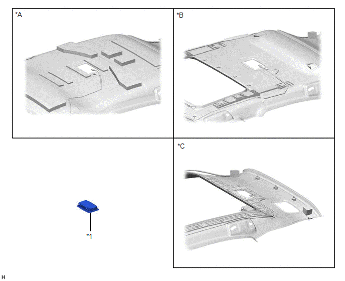
| *A | for Normal Roof | *B | for Sliding Roof |
| *C | for Glass Roof | - | - |
| *1 | SPOT LIGHT ASSEMBLY (ROOM LIGHT) | - | - |
Removal
REMOVAL
PROCEDURE
1. REMOVE SPOT LIGHT ASSEMBLY (ROOM LIGHT)
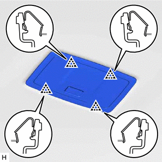
| (a) Using a screwdriver, detach the 4 clips. HINT: Tape the screwdriver tip before use. |
|
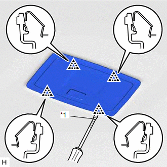
(b) Disconnect the connector and remove the spot light assembly (room light).
Inspection
INSPECTION
PROCEDURE
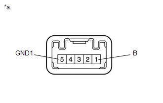
1. INSPECT SPOT LIGHT ASSEMBLY (ROOM LIGHT)
(a) Inspect the room light.
| (1) Apply battery voltage to the connector and check the light illumination condition. OK:
If the result is not as specified, replace the spot light assembly (room light). |
|
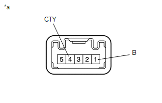
| (b) Inspect the room light (for Door-linked). (1) Apply battery voltage to the connector and check the light illumination condition. OK:
If the result is not as specified, replace the spot light assembly (room light). |
|
| (c) Inspect the switch illumination. (1) Apply battery voltage to the connector and check the light illumination condition. OK:
If the result is not as specified, replace the spot light assembly (room light). |
|
Installation
INSTALLATION
PROCEDURE
1. INSTALL SPOT LIGHT ASSEMBLY (ROOM LIGHT)
| (a) Connect the connector. |
|
(b) Attach the 4 clips to install the spot light assembly (room light).
READ NEXT:
 Vanity Light
ComponentsCOMPONENTS ILLUSTRATION *1 VANITY LIGHT ASSEMBLY *2 VANITY LIGHT BULB *3 VANITY LIGHT HOLDER - - RemovalREMOVAL CAUTION / NOTICE / HINT HINT:
Use the same procedu
Vanity Light Bulb
ReplacementREPLACEMENT CAUTION / NOTICE / HINT HINT:
Use the same procedure for the RH and LH sides.
The procedure listed below is for the LH side.
PROCEDURE 1. DISCONNECT VANITY LIGHT ASSEMB
SEE MORE:
Drive Motor "B" Position Sensor Circuit Range / Performance (P0A46-126)
DTC SUMMARY MALFUNCTION DESCRIPTION This DTC indicates that an overvoltage in the inverter has occurred. The cause of this malfunction may be one of the following: Internal inverter malfunction
Inverter internal circuit malfunction
Rear traction motor with transaxle assembly malfunction
Ope
Problem Symptoms Table
PROBLEM SYMPTOMS TABLE HINT: Use the table below to help determine the cause of problem symptoms. If multiple suspected areas are listed, the potential causes of the symptoms are listed in order of probability in the "Suspected Area" column of the table. Check each symptom by checking the suspected
