Lexus NX: Removal
REMOVAL
PROCEDURE
1. REMOVE TIMING CHAIN COVER ASSEMBLY
Click here .gif)
2. REMOVE EXHAUST MANIFOLD CONVERTER SUB-ASSEMBLY
Click here
3. REMOVE THROTTLE WITH MOTOR BODY ASSEMBLY
Click here
4. REMOVE WATER BY-PASS PIPE
Click here
5. REMOVE EGR COOLER ASSEMBLY
Click here
6. REMOVE EGR VALVE ASSEMBLY
Click here
7. REMOVE NO. 3 WATER BY-PASS HOSE
Click here
8. REMOVE NO. 1 WATER BY-PASS HOSE
Click here
9. REMOVE NO. 1 EGR PIPE
Click here
10. REMOVE INTAKE MANIFOLD
Click here
11. REMOVE FUEL DELIVERY PIPE
Click here
12. REMOVE INJECTOR VIBRATION INSULATOR
Click here
13. SET NO. 1 CYLINDER TO TDC/COMPRESSION
Click here
14. REMOVE TIMING CHAIN GUIDE
Click here
15. REMOVE NO. 1 CHAIN TENSIONER ASSEMBLY
Click here
16. REMOVE CHAIN TENSIONER SLIPPER
Click here
17. REMOVE CHAIN SUB-ASSEMBLY
Click here
18. REMOVE NO. 1 CHAIN VIBRATION DAMPER
Click here
19. REMOVE CAMSHAFT TIMING GEAR ASSEMBLY
Click here
20. REMOVE CAMSHAFT TIMING SPROCKET
Click here
21. REMOVE CAMSHAFT HOUSING SUB-ASSEMBLY
Click here
22. REMOVE CAMSHAFT BEARING CAP
Click here
23. REMOVE OIL CONTROL VALVE FILTER
Click here
24. REMOVE CAMSHAFT
Click here
25. REMOVE NO. 2 CAMSHAFT
Click here
26. REMOVE NO. 1 CAMSHAFT BEARING
Click here
27. REMOVE NO. 2 CAMSHAFT BEARING
Click here
28. REMOVE NO. 1 VALVE ROCKER ARM SUB-ASSEMBLY
Click here
29. REMOVE VALVE LASH ADJUSTER ASSEMBLY
Click here
30. REMOVE VALVE STEM CAP
Click here
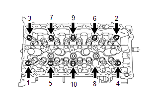
31. REMOVE CYLINDER HEAD SUB-ASSEMBLY
| (a) Using a 10 mm bi-hexagon wrench, uniformly loosen the 10 cylinder head set bolts in the sequence shown in the illustration. Remove the 10 cylinder head set bolts and plate washers. NOTICE:
HINT: Be sure to keep the removed parts separate for each installation position. |
|
(b) Remove the cylinder head sub-assembly.
32. REMOVE CYLINDER HEAD GASKET
(a) Remove the cylinder head gasket from the cylinder block.
33. INSPECT CYLINDER HEAD SET BOLT
Click here
34. INSPECT CYLINDER HEAD SUB-ASSEMBLY
Click here
READ NEXT:
 Installation
INSTALLATION CAUTION / NOTICE / HINT HINT: Perform "Inspection After Repairs" after replacing the cylinder head sub-assembly. Click here PROCEDURE 1. INSTALL CYLINDER HEAD GASKET (a) Clean the cylin
Drive Belt
ComponentsCOMPONENTS ILLUSTRATION *1 FAN AND GENERATOR V BELT *2 REAR ENGINE UNDER COVER RH On-vehicle InspectionON-VEHICLE INSPECTION PROCEDURE 1. INSPECT FAN AND GENERATOR V BELT (
SEE MORE:
DC / DC Converter Status Circuit Low Input (P0A09-265)
DESCRIPTION Refer to the description for DTC P0A08-264. Click here The hybrid vehicle control ECU sends a signal to the DC/DC converter to prohibit its control and receives signals indicating a normal or abnormal (below 11 V auxiliary battery voltage) condition of the 12 V charging system from th
Customize Parameters
CUSTOMIZE PARAMETERS INSTALL CUSTOMIZE THEFT DETERRENT SYSTEM HINT: The following items can be customized. NOTICE:
When the customer requests a change in a function, first make sure that the function can be customized.
Be sure to make a note of the current settings before customizing.
When tr
