Lexus NX: Installation
INSTALLATION
CAUTION / NOTICE / HINT
HINT:
Perform "Inspection After Repairs" after replacing the cylinder head sub-assembly.
Click here .gif)
PROCEDURE
1. INSTALL CYLINDER HEAD GASKET
(a) Clean the cylinder block and cylinder head sub-assembly with solvent.
(b) Apply a seal packing to a new cylinder head gasket as shown in the illustration.
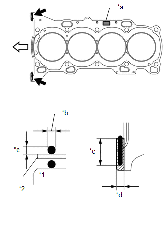
| *1 | Cylinder Block |
| *2 | Cylinder Head Gasket |
| *a | Lot No. |
| *b | 3.0 to 7.0 mm (0.118 to 0.276 in.) |
| *c | 20 mm (0.787 in.) or more |
| *d | 7.0 mm (0.276 in.) |
| *e | 3.0 mm (0.118 in.) or more |
.png) | Seal Packing Application Area |
.png) | Engine Front |
Seal packing:
Toyota Genuine Seal Packing Black, Three Bond 1207B or equivalent
Standard seal dimension:
3.0 to 7.0 mm (0.118 to 0.276 in.) wide and 3.0 mm (0.118 in.) thick
NOTICE:
- Remove any oil from the contact surface.
- Install the cylinder head gasket within 3 minutes and tighten the bolts within 15 minutes after applying seal packing.
HINT:
Apply at least 20 mm (0.787 in.) of seal packing from the inside edge of the protrusion of the cylinder block.
(c) Place a new cylinder head gasket on the cylinder block surface with the front face of the Lot No. stamp upward.
NOTICE:
Pay attention to the installation direction.
2. INSTALL CYLINDER HEAD SUB-ASSEMBLY
HINT:
Perform "Inspection After Repairs" after replacing the cylinder head sub-assembly.
Click here
(a) Place the cylinder head sub-assembly on the cylinder block.
NOTICE:
- Make sure that no oil is on the mounting surface of the cylinder head sub-assembly.
- Place the cylinder head sub-assembly on the cylinder block gently in order not to damage the gasket with the bottom part of the head.
HINT:
The cylinder head set bolts are tightened in 4 progressive steps.
(b) Install the plate washers to the cylinder head set bolts.
(c) Apply a light coat of engine oil to the threads and under the heads of the cylinder head set bolts.
(d) Step 1:
| (1) Using a 10 mm bi-hexagon wrench, install and uniformly tighten the 10 cylinder head set bolts in several steps in the sequence shown in the illustration. Torque: 36 N·m {367 kgf·cm, 27 ft·lbf} NOTICE: Do not drop the plate washers for the cylinder head set bolt into the cylinder head sub-assembly. |
|
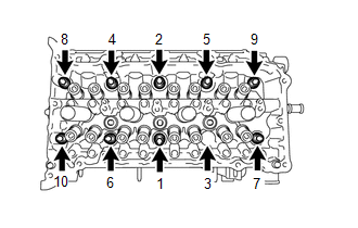
(e) Step 2:
(1) Tighten the cylinder head set bolts again in the sequence shown in the illustration to make sure that they are tightened to the specified torque.
Torque:
36 N·m {367 kgf·cm, 27 ft·lbf}
(f) Step 3:
(1) Mark the front side of each cylinder head set bolt head with paint.
(2) Tighten the cylinder head set bolts 90° in the sequence shown in step 1.
(g) Step 4:
(1) Tighten the cylinder head set bolts another 90° in the sequence shown in step 1.
(2) Check that the paint marks are now at a 180° angle to the front.
NOTICE:
- Do not apply oil for at least 4 hours after the installation.
- Do not start the engine for at least 4 hours after the installation.
- After the installation, if the seal packing has seeped out, wipe it off.
3. INSTALL VALVE STEM CAP
Click here
4. INSTALL VALVE LASH ADJUSTER ASSEMBLY
Click here
5. INSTALL NO. 1 VALVE ROCKER ARM SUB-ASSEMBLY
Click here
6. INSTALL NO. 2 CAMSHAFT BEARING
Click here
7. INSTALL NO. 1 CAMSHAFT BEARING
Click here
8. INSTALL NO. 2 CAMSHAFT
Click here
9. INSTALL CAMSHAFT
Click here
10. INSTALL OIL CONTROL VALVE FILTER
Click here
11. INSTALL CAMSHAFT BEARING CAP
Click here
12. INSTALL CAMSHAFT HOUSING SUB-ASSEMBLY
Click here
13. INSTALL CAMSHAFT TIMING GEAR ASSEMBLY
Click here
14. INSTALL CAMSHAFT TIMING SPROCKET
Click here
15. ADD ENGINE OIL
Click here
16. INSTALL NO. 1 CHAIN VIBRATION DAMPER
Click here
17. INSTALL CHAIN SUB-ASSEMBLY
Click here
18. INSTALL CHAIN TENSIONER SLIPPER
Click here
19. INSTALL NO. 1 CHAIN TENSIONER ASSEMBLY
Click here
20. INSTALL TIMING CHAIN GUIDE
Click here
21. CHECK NO. 1 CYLINDER TO TDC/COMPRESSION
Click here
22. INSTALL INJECTOR VIBRATION INSULATOR
Click here
23. INSTALL FUEL DELIVERY PIPE
Click here
24. INSTALL INTAKE MANIFOLD
Click here
25. TEMPORARILY INSTALL NO. 1 EGR PIPE
Click here
26. INSTALL NO. 1 WATER BY-PASS HOSE
Click here
27. INSTALL NO. 3 WATER BY-PASS HOSE
Click here
28. TEMPORARILY INSTALL EGR VALVE ASSEMBLY
Click here
29. TEMPORARILY INSTALL EGR COOLER ASSEMBLY
Click here
30. INSTALL WATER BY-PASS PIPE
Click here
31. TIGHTEN NO. 1 EGR PIPE
Click here
32. TIGHTEN EGR COOLER ASSEMBLY
Click here
33. TIGHTEN EGR VALVE ASSEMBLY
Click here
34. INSTALL THROTTLE WITH MOTOR BODY ASSEMBLY
Click here
35. INSTALL EXHAUST MANIFOLD CONVERTER SUB-ASSEMBLY
Click here
36. INSTALL TIMING CHAIN COVER ASSEMBLY
Click here
READ NEXT:
 Drive Belt
ComponentsCOMPONENTS ILLUSTRATION *1 FAN AND GENERATOR V BELT *2 REAR ENGINE UNDER COVER RH On-vehicle InspectionON-VEHICLE INSPECTION PROCEDURE 1. INSPECT FAN AND GENERATOR V BELT (
On-vehicle Inspection
ON-VEHICLE INSPECTION PROCEDURE 1. INSPECT ENGINE COOLANT Click here 2. INSPECT ENGINE OIL Click here 3. INSPECT AUXILIARY BATTERY Click here 4. INSPECT AIR CLEANER FILTER ELEMENT SUB-ASSEMBLY (
SEE MORE:
Inspection
INSPECTION PROCEDURE 1. INSPECT THROTTLE WITH MOTOR BODY ASSEMBLY *a Component without harness connected (Throttle with Motor Body Assembly) (a) Check that the throttle valve opens and closes smoothly. (b) Check that the there is no sludge accumulating around the throttle with motor body as
Removal
REMOVAL CAUTION / NOTICE / HINT PROCEDURE 1. REMOVE ELECTRIC POWER STEERING COLUMN SUB-ASSEMBLY Click here 2. REMOVE POWER STEERING ECU ASSEMBLY (a) Detach the claw and remove the power steering ECU protector from the power steering ECU assembly. (b) Remove the 2 cable ties and h
