Lexus NX: Removal
REMOVAL
CAUTION / NOTICE / HINT
NOTICE:
- Do not replace the spiral with sensor cable sub-assembly with the battery connected and the engine switch on (IG).
- Do not rotate the spiral with sensor cable sub-assembly when the following conditions are met: 1) The steering wheel is removed, 2) the battery is connected,and 3) the engine switch is on (IG).
- Ensure that the steering wheel is installed and aligned straight when inspecting the steering sensor.
PROCEDURE
1. PLACE FRONT WHEELS FACING STRAIGHT AHEAD
2. REMOVE STEERING WHEEL ASSEMBLY
Click here .gif)
3. REMOVE LOWER STEERING COLUMN COVER
NOTICE:
Failure to follow the correct removal procedure may damage the claws.
| (a) Remove the 2 screws. |
|
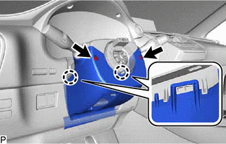
(b) Release the tilt lever.
(c) Press both sides of the lower steering column cover to detach the 2 claws.
(d) Pull the steering column lower cover toward the rear of the vehicle and detach the lower side claw to remove the steering column lower cover.
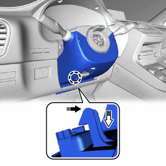
 | Remove in this Direction (1) |
 | Remove in this Direction (2) |
NOTICE:
- If the steering column is pushed downward with heavy force before the claw is detached, the resin stay attachment may become damaged.
- Do not damage the tilt and telescopic switch.
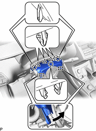
4. REMOVE UPPER STEERING COLUMN COVER
| (a) Detach the 3 claws, 4 clips and 2 pins and remove the upper steering column cover. |
|
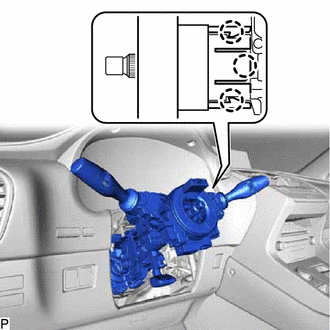
5. REMOVE COMBINATION SWITCH ASSEMBLY WITH SPIRAL CABLE SUB-ASSEMBLY
(a) Disconnect the connectors from the combination switch assembly with spiral cable sub-assembly.
| (b) Detach the 3 claws. Remove the combination switch assembly with spiral cable sub-assembly from the electric power steering column sub-assembly. |
|
6. REMOVE UPPER INSTRUMENT PANEL SUB-ASSEMBLY
Click here
7. REMOVE LOWER NO. 1 INSTRUMENT PANEL AIRBAG ASSEMBLY
Click here
8. REMOVE COLUMN HOLE COVER SILENCER SHEET
| (a) Fold back the floor carpet, and then remove the 2 clips and column hole cover silencer sheet. |
|
9. DISCONNECT NO. 2 STEERING INTERMEDIATE SHAFT ASSEMBLY
| (a) Place matchmarks on the steering intermediate shaft and No. 2 steering intermediate shaft assembly. |
|
(b) Remove the bolt.
(c) Disconnect the No. 2 steering intermediate shaft assembly from the steering intermediate shaft assembly.
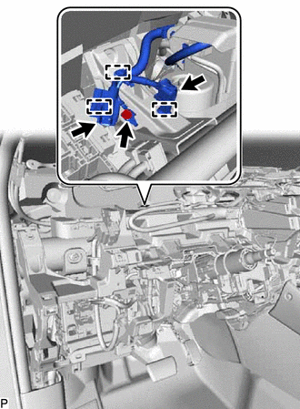
10. REMOVE NO. 1 AIR DUCT
| (a) Detach the 3 claws and remove the No. 1 air duct. NOTICE:
|
|
11. REMOVE ELECTRIC POWER STEERING COLUMN SUB-ASSEMBLY
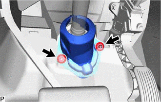
| (a) Disconnect the 2 connectors and detach the 3 clamps. |
|
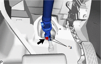
(b) Remove the bolt and disconnect the harness cable.
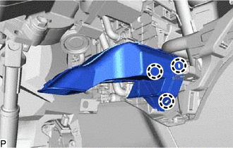
| (c) Remove the bolt, 2 nuts and electric power steering column sub-assembly. NOTICE:
|
|
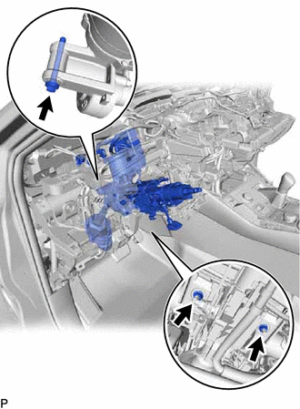
12. REMOVE NO. 2 STEERING INTERMEDIATE SHAFT ASSEMBLY
(a) Remove the bolt.
NOTICE:
Do not remove the No. 2 steering intermediate shaft assembly from the electric power steering column sub-assembly.
| (b) Put matchmarks on the No. 2 steering intermediate shaft assembly and electric power steering column sub-assembly. |
|
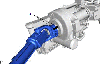
(c) Remove the No. 2 steering intermediate shaft assembly from the electric power steering column sub-assembly.
READ NEXT:
 Disassembly
DISASSEMBLY CAUTION / NOTICE / HINT NOTICE:
When using a vise, place aluminum plates between the part and vise.
When using a vise, do not overtighten it.
PROCEDURE 1. REMOVE STEERING LOCK ACTU
Inspection
INSPECTION CAUTION / NOTICE / HINT NOTICE:
When using a vise, place aluminum plates between the part and vise.
When using a vise, do not overtighten it.
PROCEDURE 1. INSPECT ELECTRIC POWER STE
Reassembly
REASSEMBLY CAUTION / NOTICE / HINT NOTICE:
When using a vise, place aluminum plates between the part and vise.
When using a vise, do not overtighten it.
PROCEDURE 1. INSTALL POWER STEERING MOT
SEE MORE:
Problem Symptoms Table
PROBLEM SYMPTOMS TABLE HINT:
Inspect the fuses and relays related to this system before inspecting the suspected areas below.
If the problem only occurs in certain locations or at certain times of day, check for wave interference.
If optional components are installed, check for wave interfere
Wireless-linked Return Function does not Operate
DESCRIPTION When a door is unlocked using the wireless unlock function, the certification ECU (smart key ECU assembly) sends a key ID signal to the main body ECU (multiplex network body ECU). When a door is unlocked using the entry unlock function, the certification ECU (smart key ECU assembly) send
