Lexus NX: Removal
REMOVAL
CAUTION / NOTICE / HINT
NOTICE:
- Do not replace the spiral with sensor cable sub-assembly with the battery connected and the power switch on (IG).
- Do not rotate the spiral with sensor cable sub-assembly when the following conditions are met: 1) The steering wheel is removed, 2) the battery is connected,and 3) the power switch is on (IG).
- Ensure that the steering wheel is installed and aligned straight when inspecting the steering sensor.
PROCEDURE
1. PLACE FRONT WHEELS FACING STRAIGHT AHEAD
2. CUSTOMIZE POWER TILT AND POWER TELESCOPIC STEERING COLUMN SYSTEM
(a) Disable the auto tilt away function by changing the customize parameter.
Click here .gif)
NOTICE:
Record the current customize parameter setting (whether the auto tilt away function is enabled or disabled) in order to restore the current setting after finishing the operation.
HINT:
Performing the above operation causes the auto tilt away function to be disabled when the power switch is turned off.
(b) Turn the power switch on (IG). Operate the tilt and telescopic switch to fully extend and lower the steering column assembly.
3. REMOVE STEERING WHEEL ASSEMBLY
Click here
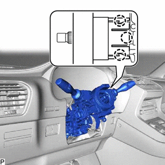
4. REMOVE LOWER STEERING COLUMN COVER
NOTICE:
Failure to follow the correct removal procedure may damage the claws.
| (a) Remove the 3 screws. |
|
(b) Detach the 2 claws and remove the lower steering column cover.
NOTICE:
Do not damage the tilt and telescopic switch.
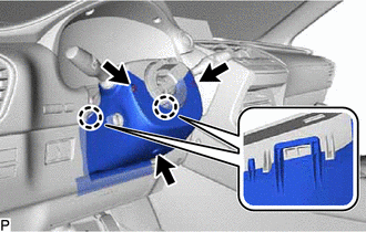
5. REMOVE UPPER STEERING COLUMN COVER
| (a) Detach the 3 claws, 4 clips and 2 pins and remove the upper steering column cover. |
|
.png)
6. REMOVE COMBINATION SWITCH ASSEMBLY WITH SPIRAL CABLE SUB-ASSEMBLY
(a) Disconnect the connectors from the combination switch assembly with spiral cable sub-assembly.
| (b) Detach the 3 claws. Remove the combination switch assembly with spiral cable sub-assembly from the electric power steering column sub-assembly. |
|
7. REMOVE UPPER INSTRUMENT PANEL SUB-ASSEMBLY
Click here
8. REMOVE LOWER NO. 1 INSTRUMENT PANEL AIRBAG ASSEMBLY
Click here
9. REMOVE COLUMN HOLE COVER SILENCER SHEET
| (a) Fold back the floor carpet, and then remove the 2 clips and column hole cover silencer sheet. |
|
.png)
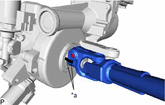
10. DISCONNECT NO. 2 STEERING INTERMEDIATE SHAFT ASSEMBLY
| (a) Place matchmarks on the steering intermediate shaft and No. 2 steering intermediate shaft assembly. |
|
.png)
(b) Remove the bolt.
(c) Disconnect the No. 2 steering intermediate shaft assembly from the steering intermediate shaft assembly.
11. REMOVE NO. 1 AIR DUCT
| (a) Detach the 3 claws and remove the No. 1 air duct. NOTICE:
|
|
.png)
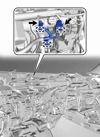
12. REMOVE ELECTRIC POWER STEERING COLUMN SUB-ASSEMBLY
| (a) Disconnect the 2 connectors and detach the 3 clamps. |
|
(b) Remove the bolt and disconnect the harness cable.
| (c) Remove the bolt, 2 nuts and electric power steering column sub-assembly. NOTICE: Do not drop or strike the electric power steering column sub-assembly. If dropped or struck, replace it with a new one. |
|
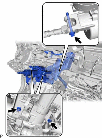
13. REMOVE NO. 2 STEERING INTERMEDIATE SHAFT ASSEMBLY
(a) Remove the bolt.
NOTICE:
Do not remove the No. 2 steering intermediate shaft assembly from the electric power steering column sub-assembly.
| (b) Put matchmarks on the No. 2 steering intermediate shaft assembly and electric power steering column sub-assembly. |
|
(c) Remove the No. 2 steering intermediate shaft assembly from the electric power steering column sub-assembly.
READ NEXT:
 Disassembly
DISASSEMBLY CAUTION / NOTICE / HINT NOTICE:
When using a vise, place aluminum plates between the part and vise.
When using a vise, do not overtighten it.
PROCEDURE 1. REMOVE STEERING LOCK ACTU
Inspection
INSPECTION CAUTION / NOTICE / HINT NOTICE:
When using a vise, place aluminum plates between the part and vise.
When using a vise, do not overtighten it.
PROCEDURE 1. INSPECT ELECTRIC POWER STE
Installation
INSTALLATION CAUTION / NOTICE / HINT NOTICE:
Do not replace the spiral with sensor cable sub-assembly with the battery connected and the power switch on (IG).
Do not rotate the spiral with sensor
SEE MORE:
Seat belts
Make sure that all occupants are
wearing their seat belts before driving
the vehicle.
WARNING
Observe the following precautions to
reduce the risk of injury in the event of
sudden braking, sudden swerving or an
accident.
Failure to do so may cause death or serious
injury.
■Wearing a se
Short in Side Squib (RH) Circuit (B1820-B1823)
DESCRIPTION The front side squib RH circuit consists of the airbag ECU assembly and front seat airbag assembly RH. This circuit instructs the SRS to deploy when deployment conditions are met. These DTCs are stored when a malfunction is detected in the front side squib RH circuit. DTC No. Detect
