Lexus NX: Inspection
INSPECTION
CAUTION / NOTICE / HINT
NOTICE:
- When using a vise, place aluminum plates between the part and vise.
- When using a vise, do not overtighten it.
PROCEDURE
1. INSPECT ELECTRIC POWER STEERING COLUMN SUB-ASSEMBLY
(a) Inspect the preload.
| (1) Secure the electric power steering column sub-assembly in a vise between aluminum plates or pieces of cloth as shown in the illustration. NOTICE:
|
|
.png)
(2) Install the 2 nuts to the electric power steering column sub-assembly.
HINT:
The nuts to use are the steering wheel set nut or equivalents.
| Steering wheel set nut part No. | Thread diameter | Thread pitch |
|---|---|---|
| 90179-12071 | 12 mm (0.4724 in.) | 1.25 mm (0.0492 in.) |
| (3) Turn the steering main shaft by 180° to the left and right at a speed of 1 turn per second. Repeat these movements 2 to 3 times to center the power steering ECU assembly. |
|
.png)
| (4) Check the turning torque of the steering main shaft. Standard preload: 0.9 to 1.5 N*m (10 to 15 kgf*cm, 8 to 13 in.*lbf) NOTICE: Make sure that the shaft turns smoothly. HINT: If the result is not as specified, center the power steering ECU assembly again. |
|
.png)
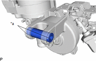
(b) Inspect the bushings.
| (1) Check that the 2 bushings are securely installed to the electric power steering column sub-assembly. HINT: If the bushings are missing or damaged, replace the electric power steering column sub-assembly with a new one. |
|
READ NEXT:
 Installation
INSTALLATION CAUTION / NOTICE / HINT NOTICE:
Do not replace the spiral with sensor cable sub-assembly with the battery connected and the power switch on (IG).
Do not rotate the spiral with sensor
Steering Heater Switch
InspectionINSPECTION PROCEDURE 1. REMOVE NO. 2 COMBINATION SWITCH ASSEMBLY Click here 2. INSPECT NO. 2 COMBINATION SWITCH ASSEMBLY (a) Measure the voltage according to the value (s) in the table
SEE MORE:
Rear Door LH ECU Communication Stop (B2324)
DESCRIPTION This DTC is output when LIN communication between the rear power window regulator motor assembly LH and main body ECU (multiplex network body ECU) stops for 10 seconds or more. DTC No. Detection Item DTC Detection Condition Trouble Area B2324 Rear Door LH ECU Communication
Components
COMPONENTS ILLUSTRATION *1 CLEARANCE LIGHT ASSEMBLY LH - -
