Lexus NX: Disassembly
DISASSEMBLY
CAUTION / NOTICE / HINT
NOTICE:
- When using a vise, place aluminum plates between the part and vise.
- When using a vise, do not overtighten it.
PROCEDURE
1. REMOVE STEERING LOCK ACTUATOR ASSEMBLY
(a) Secure the electric power steering column sub-assembly in a vise.
(b) Using a center punch, mark the center of the 2 tapered-head bolts.
(c) Using a 3 to 4 mm (0.119 to 0.157 in.) drill, drill a hole in the 2 bolts.
| (d) Using a screw extractor, remove the 2 bolts and steering lock actuator assembly from the electric power steering column sub-assembly. |
|
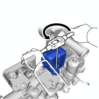
2. REMOVE POWER STEERING ECU ASSEMBLY
Click here .gif)
3. REMOVE MULTIPLEX TILT AND TELESCOPIC ECU
Click here
READ NEXT:
 Inspection
INSPECTION CAUTION / NOTICE / HINT NOTICE:
When using a vise, place aluminum plates between the part and vise.
When using a vise, do not overtighten it.
PROCEDURE 1. INSPECT ELECTRIC POWER STE
Installation
INSTALLATION CAUTION / NOTICE / HINT NOTICE:
Do not replace the spiral with sensor cable sub-assembly with the battery connected and the power switch on (IG).
Do not rotate the spiral with sensor
Steering Heater Switch
InspectionINSPECTION PROCEDURE 1. REMOVE NO. 2 COMBINATION SWITCH ASSEMBLY Click here 2. INSPECT NO. 2 COMBINATION SWITCH ASSEMBLY (a) Measure the voltage according to the value (s) in the table
SEE MORE:
Entry Unlock and Unlatch Functions do not Operate Using Kick Sensor
DESCRIPTION If the hands free power back door operation does not operate, it could indicate the certification ECU (smart key ECU assembly) did not transmit a power back door open request signal, or a malfunction in the power back door system. CAUTION / NOTICE / HINT NOTICE:
The smart access syste
Reassembly
REASSEMBLY CAUTION / NOTICE / HINT HINT:
Use the same procedure for the RH and LH sides.
The procedure listed below is for the LH side.
PROCEDURE 1. INSTALL FRONT TURN SIGNAL LIGHT BULB (a) Install the front turn signal light bulb to the bulb socket. (b) Align the matchmark of the bulb socke
© 2016-2026 Copyright www.lexunx.com
