Lexus NX: Removal
REMOVAL
PROCEDURE
1. PRECAUTION
NOTICE:
After turning the power switch is turned off, there may be a waiting time before disconnecting the auxiliary negative (-) battery terminal.
Click here .gif)
2. CUSTOMIZE POWER TILT AND POWER TELESCOPIC STEERING COLUMN SYSTEM
(a) Disable the auto tilt away function by changing the customize parameter.
Click here
NOTICE:
Record the current customize parameter setting (whether the auto tilt away function is enabled or disabled) in order to restore the current setting after finishing the operation.
HINT:
Performing the above operation causes the auto tilt away function to be disabled when the power switch is turned off.
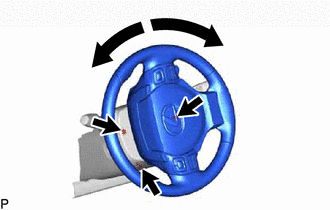
(b) Turn the power switch on (IG). Operate the tilt and telescopic switch to fully extend and lower the steering column assembly.
3. REMOVE NO. 3 DECK BOARD SUB-ASSEMBLY
Click here
4. REMOVE REAR DECK FLOOR BOX
Click here
5. REMOVE DECK FLOOR BOX LH
Click here
6. DISCONNECT CABLE FROM NEGATIVE AUXILIARY BATTERY TERMINAL
7. ALIGN FRONT WHEELS FACING STRAIGHT AHEAD
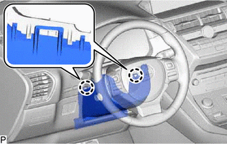
8. REMOVE LOWER STEERING COLUMN COVER
| (a) Remove the 3 screws. |
|
| (b) Detach the 2 claws and remove the lower steering column cover. NOTICE: Do not damage the tilt and telescopic switch. |
|
9. REMOVE TILT AND TELESCOPIC SWITCH
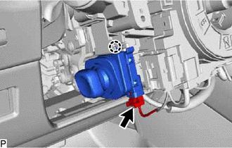
(a) Disconnect the connector.
(b) Detach the claw and pull out the tilt and telescopic switch.
NOTICE:
Pushing on the claw too hard will break the claw.
READ NEXT:
 Inspection
INSPECTION PROCEDURE 1. INSPECT TILT AND TELESCOPIC SWITCH (a) Measure the resistance according to the value(s) in the table below. Standard Resistance: Tester Connection Switch Condition S
Installation
INSTALLATION PROCEDURE 1. INSTALL TILT AND TELESCOPIC SWITCH (a) Attach the claw to install the tilt and telescopic switch. (b) Connect the connector. 2. INSTALL LOWER STEERING COLUMN COVER (a) Attach
SEE MORE:
Operation Check
OPERATION CHECK AFS (FRONT-LIGHTING ADAPTIVE SYSTEM) OPERATION CHECK NOTICE: Make sure that the customize settings are set to default when performing the AFS (front-lighting adaptive system) operation check. (a) Perform the following operation with the low beam headlights on and check that the headl
Front Passenger Side Door Entry Lock Function does not Operate
DESCRIPTION If the entry lock function does not operate for the front passenger door only, but the entry unlock function operates, the request code is being transmitted properly from the for passenger door. In this case, there may be a problem related to the lock sensor (connection between the certi
