Lexus NX: Removal
REMOVAL
CAUTION / NOTICE / HINT
NOTICE:
- When the brake pedal is first depressed after replacing the brake pads or pushing back the disc brake piston, DTC C1214 may be output. As there is no malfunction, clear the DTC.
- While the auxiliary battery is connected, even if the power switch is off, the brake control system activates when the brake pedal is depressed or the door courtesy switch is turned on. Therefore, even if only brake shoes are to be removed and installed, be sure to perform the Disable Brake Control procedure and disconnect the cable from the negative (-) terminal of the auxiliary battery before beginning work.
HINT:
- Use the same procedure for the RH and LH sides.
- The procedure listed below is for the LH side.
PROCEDURE
1. REMOVE FRONT AXLE ASSEMBLY LH
Click here .gif)
2. REMOVE FRONT LOWER BALL JOINT ASSEMBLY LH
| (a) Secure the front axle assembly between aluminum plates in a vise. NOTICE: When using a vise, do not overtighten it. |
|
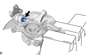
(b) Remove the clip and nut.
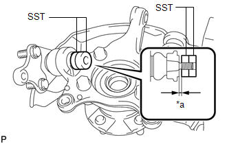
| (c) Install SST to the front lower ball joint as shown in the illustration. SST: 09960-20010 09961-02050 09961-02050 NOTICE: Make sure that the clearance measurement between SST and the front axle assembly is 1 mm (0.0394 in.). |
|
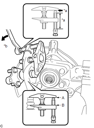
| (d) Using SST, remove the front lower ball joint from the front axle assembly as shown in the illustration. SST: 09960-20010 09961-02010 09961-02050 09961-02050 CAUTION: Apply molybdenum grease to the bolt threads and the tip of SST. NOTICE:
|
|
READ NEXT:
 Inspection
INSPECTION PROCEDURE 1. INSPECT FRONT LOWER BALL JOINT ASSEMBLY LH (a) Inspect the turning torque of the ball joint. (1) Secure the front lower ball joint in a vise using aluminum plates. (2) Insta
Installation
INSTALLATION CAUTION / NOTICE / HINT NOTICE:
When the brake pedal is first depressed after replacing the brake pads or pushing back the disc brake piston, DTC C1214 may be output. As there is no ma
Front Lower Suspension Arm
ComponentsCOMPONENTS ILLUSTRATION *1 FRONT LOWER NO. 1 SUSPENSION ARM SUB-ASSEMBLY LH *2 FRONT SUSPENSION CROSSMEMBER SUB-ASSEMBLY N*m (kgf*cm, ft.*lbf): Specified torque * For u
SEE MORE:
Refrigerant Line
ComponentsCOMPONENTS ILLUSTRATION *1 LIQUID TUBE SUB-ASSEMBLY *2 DISCHARGE HOSE SUB-ASSEMBLY *3 SUCTION HOSE SUB-ASSEMBLY *4 AIR CONDITIONER TUBE AND ACCESSORY ASSEMBLY *5 PIPING CLAMP *6 O-RING N*m (kgf*cm, ft.*lbf): Specified torque ● Non-reusable part
Collision has been detected or Collision Sensor Connection (Open) (P1606-308,P1606-317)
DTC SUMMARY MALFUNCTION DESCRIPTION The hybrid vehicle control ECU and airbag ECU detect that a collision has occurred and shut off the system main relay. The cause of this DTC may be one of the following:
Collision is detected
Detection sensor system malfunction
Airbag system malfunction
