Lexus NX: Front Lower Suspension Arm
Components
COMPONENTS
ILLUSTRATION
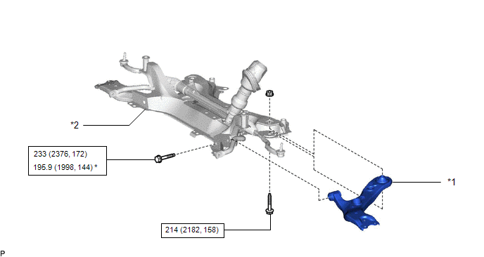
| *1 | FRONT LOWER NO. 1 SUSPENSION ARM SUB-ASSEMBLY LH | *2 | FRONT SUSPENSION CROSSMEMBER SUB-ASSEMBLY |
.png) | N*m (kgf*cm, ft.*lbf): Specified torque | * | For use with SST |
Removal
REMOVAL
CAUTION / NOTICE / HINT
HINT:
- Use the same procedure for the RH and LH sides.
- The procedure listed below is for the LH side.
PROCEDURE
1. REMOVE FRONT SUSPENSION CROSSMEMBER SUB-ASSEMBLY
Click here .gif)
2. REMOVE FRONT LOWER NO. 1 SUSPENSION ARM SUB-ASSEMBLY LH
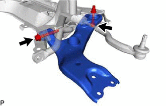
| (a) Remove the 2 bolts, nut and front lower No. 1 suspension arm sub-assembly LH from the front suspension crossmember sub-assembly. NOTICE: Because the nut has its own stopper, do not turn the nut. Loosen the bolt with the nut secured. |
|
Installation
INSTALLATION
CAUTION / NOTICE / HINT
HINT:
- Use the same procedure for the RH and LH sides.
- The procedure listed below is for the LH side.
PROCEDURE
1. TEMPORARILY INSTALL FRONT LOWER NO. 1 SUSPENSION ARM SUB-ASSEMBLY LH
(a) Temporarily install the front lower No. 1 suspension arm sub-assembly LH to the front suspension crossmember sub-assembly with the 2 bolts and nut.
NOTICE:
Because the nut has its own stopper, do not turn the nut. Tighten the bolt with the nut fixed in place.
2. INSTALL FRONT SUSPENSION CROSSMEMBER SUB-ASSEMBLY
Click here .gif)
3. INSTALL FRONT WHEELS
Click here
4. STABILIZE SUSPENSION
(a) Lower the vehicle.
(b) Bounce the vehicle up and down at the corners several times to stabilize the suspension.
5. TIGHTEN FRONT LOWER NO. 1 SUSPENSION ARM SUB-ASSEMBLY LH
(a) Using SST, tighten bolt A.
SST: 09961-01270
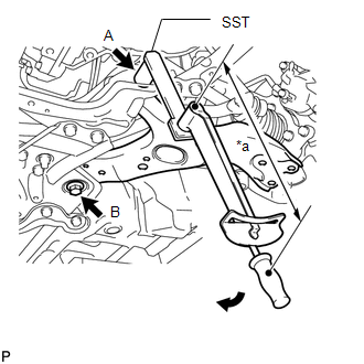
| *a | Torque Wrench Fulcrum Length |
.png) | Turn |
Torque:
Specified tightening torque :
233 N·m {2376 kgf·cm, 172 ft·lbf}
HINT:
-
Calculate the torque wrench reading when changing the fulcrum length of the torque wrench.
Click here
- When using SST (fulcrum length of 200 mm (7.8740 in.)) + torque wrench (fulcrum length of 1055 mm (41.5354 in.)): 195.9 N*m (1998 kgf*cm, 144 ft.*lbf)
(b) Tighten bolt B.
Torque:
214 N·m {2182 kgf·cm, 158 ft·lbf}
NOTICE:
Since a stopper nut is used, tighten the bolt.
6. INSPECT AND ADJUST FRONT WHEEL ALIGNMENT
Click here
READ NEXT:
 Components
COMPONENTS ILLUSTRATION *A w/o AVS - - *1 FRONT FLEXIBLE HOSE *2 FRONT SHOCK ABSORBER WITH COIL SPRING *3 FRONT SPEED SENSOR LH *4 FRONT STABILIZER LINK ASSEMBLY LH *
Removal
REMOVAL CAUTION / NOTICE / HINT HINT:
Use the same procedure for the RH and LH sides.
The procedure listed below is for the LH side.
SST used when removing/installing the coil spring are shown
SEE MORE:
Problem Symptoms Table
PROBLEM SYMPTOMS TABLE NOTICE: If the main body ECU (multiplex network body ECU) is replaced, refer to Registration. Click here HINT:
Use the table below to help determine the cause of problem symptoms. If multiple suspected areas are listed, the potential causes of the symptoms are listed in
Parking brake
The parking brake can be set or
released automatically or manually.
In automatic mode, the parking
brake can be set or released automatically
according to shift lever
operation. Also, even in automatic
mode, the parking brake can be set
or released manually.
Operating instructions
■ Tur
