Lexus NX: Removal
REMOVAL
PROCEDURE
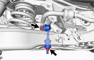
1. REMOVE REAR STABILIZER LINK ASSEMBLY LH
| (a) Remove the 2 nuts and 2 cushions and disconnect the rear stabilizer link assembly LH from the rear No. 2 suspension arm assembly LH. HINT: If the ball joint turns together with the nut, use a 6 mm hexagon wrench to hold the stud. |
|
2. REMOVE REAR STABILIZER LINK ASSEMBLY RH
HINT:
Use the same procedure described for the LH side.
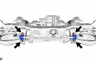
3. REMOVE REAR NO. 1 STABILIZER BAR BRACKET
| (a) Remove the 4 nuts and 2 rear No. 1 stabilizer bar brackets from the suspension member. |
|
4. REMOVE REAR STABILIZER BAR
(a) Remove the rear stabilizer bar from the rear suspension member.
5. REMOVE REAR STABILIZER BUSHING
(a) Remove the 2 rear stabilizer bushings from the rear stabilizer bar.
READ NEXT:
 Inspection
INSPECTION CAUTION / NOTICE / HINT HINT:
Use the same procedure for the RH and LH sides.
The procedure listed below is for the LH side.
PROCEDURE 1. INSPECT REAR STABILIZER LINK ASSEMBLY LH N
Installation
INSTALLATION PROCEDURE 1. INSTALL REAR STABILIZER BUSHING (a) Install the 2 rear stabilizer bushings to the rear stabilizer bar on the outside of the bush stoppers as shown in the illustration. NOTIC
SEE MORE:
Installation
INSTALLATION PROCEDURE 1. INSTALL NO. 2 FOLD SEAT SWITCH ASSEMBLY (for Rear Side) (a) Connect the connector. (b) Attach the 2 claws to install the No. 2 fold seat switch assembly. 2. INSTALL REAR POWER SEAT SWITCH (for Rear Seat) HINT: Use the same procedure for both re
Rear Right Sensor Malfunction (C1AE9)
DESCRIPTION The rear corner ultrasonic sensor (RR sensor) is installed to the rear bumper. The clearance warning ECU assembly detects obstacles based on signals received from the rear corner ultrasonic sensor (RR sensor). If the rear corner ultrasonic sensor (RR sensor) has an open circuit or other
© 2016-2026 Copyright www.lexunx.com
