Lexus NX: Removal
REMOVAL
PROCEDURE
1. PRECAUTION
CAUTION:
Be sure to read Precoution thoroughly before serving.
Click here .gif)
NOTICE:
After the power switch is turned off, there may be a waiting time before disconnecting the negative (-) auxiliary battery terminal.
Click here
2. REMOVE NO. 3 DECK BOARD SUB-ASSEMBLY
Click here
3. REMOVE REAR DECK FLOOR BOX
Click here
4. REMOVE DECK FLOOR BOX LH
Click here
5. DISCONNECT CABLE FROM NEGATIVE AUXILIARY BATTERY TERMINAL
Click here
CAUTION:
Wait at least 90 seconds after disconnecting the cable from the negative (-) auxiliary battery terminal to disable the SRS system.
6. REMOVE GLOVE COMPARTMENT DOOR ASSEMBLY
Click here
7. REMOVE NO. 2 INSTRUMENT PANEL UNDER COVER SUB-ASSEMBLY
Click here
8. REMOVE ECU INTEGRATION BOX RH
Click here
9. REMOVE VEHICLE APPROACHING SPEAKER CONTROLLER
(a) Remove the bolt.
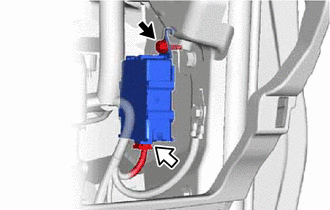
.png) | Bolt |
.png) | Connector |
(b) Detach the hook and remove the vehicle approaching speaker controller.
NOTICE:
- When removing the vehicle approaching speaker controller, take care not to damage it.
- Do not reuse a vehicle approaching speaker controller that has been dropped or subjected to a strong shock.
(c) Disconnect the connector.
READ NEXT:
 Installation
INSTALLATION PROCEDURE 1. INSTALL VEHICLE APPROACHING SPEAKER CONTROLLER (a) Connect the connector. (b) Attach the hook to install the vehicle approaching speaker controller. NOTICE:
When installin
SEE MORE:
Installation
INSTALLATION PROCEDURE 1. INSTALL INTEGRATION CONTROL AND PANEL ASSEMBLY (BRAKE HOLD SWITCH) (a) Install the integration control and panel assembly (brake hold switch) to the upper rear console panel sub-assembly with the 2 screws. HINT: The locations labeled A in the illustration are tightened t
SRS Warning Light Remains ON
DESCRIPTION The SRS warning light is located in the combination meter assembly. When the SRS is normal, the SRS warning light comes on for approximately 6 seconds after the power switch is turned from off on (IG), and then goes off automatically. If there is a malfunction in the SRS, the SRS warning
