Lexus NX: Removal
REMOVAL
CAUTION / NOTICE / HINT
HINT:
- Use the same procedure for the RH and LH sides.
- The procedure listed below is for the LH side.
PROCEDURE
1. REMOVE BACK DOOR CENTER GARNISH
Click here .gif)
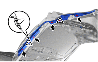
2. REMOVE BACK DOOR SIDE GARNISH LH
Click here
3. REMOVE BACK DOOR SIDE GARNISH RH
Click here
4. REMOVE BACK DOOR TRIM BASE
Click here
5. REMOVE PULL HANDLE
Click here
6. REMOVE BACK DOOR LOCK COVER
Click here
7. REMOVE BACK DOOR TRIM BOARD ASSEMBLY
Click here
8. REMOVE POWER BACK DOOR SENSOR ASSEMBLY LH
| (a) Disconnect the connector. |
|
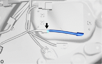
| (b) Remove the 4 screws. |
|
(c) Detach the 2 clips and remove the power back door sensor assembly LH.
READ NEXT:
 Inspection
INSPECTION PROCEDURE 1. INSPECT POWER BACK DOOR SENSOR ASSEMBLY LH (a) Measure the resistance according to the value(s) in the table below. Standard Resistance: Tester Connection Condition
Installation
INSTALLATION CAUTION / NOTICE / HINT HINT:
Use the same procedure for the RH and LH sides.
The procedure listed below is for the LH side.
PROCEDURE 1. INSTALL POWER BACK DOOR SENSOR ASSEMBLY L
SEE MORE:
Removal
REMOVAL CAUTION / NOTICE / HINT CAUTION: As the engine assembly with transaxle is extremely heavy, the engine lifter may suddenly drop if the instructions listed in the repair manual are not followed. Therefore, always follow the instructions listed in the repair manual when performing this procedur
Communication Error from VSC to HV ECU (P1630)
DESCRIPTION The skid control ECU (brake booster with master cylinder assembly) sends signals such as brake request signals to the hybrid vehicle control ECU. If an abnormal signal is detected, the hybrid vehicle control ECU stores DTC P1630. DTC No. Detection Item DTC Detection Condition Tr
© 2016-2026 Copyright www.lexunx.com
