Lexus NX: Removal
REMOVAL
PROCEDURE
1. PRECAUTION
NOTICE:
After the power switch is turned off, there may be a waiting time before disconnecting the negative (-) auxiliary battery terminal.
Click here .gif)
2. REMOVE NO. 3 DECK BOARD SUB-ASSEMBLY
Click here
3. REMOVE REAR DECK FLOOR BOX
Click here
4. REMOVE DECK FLOOR BOX LH
Click here
5. DISCONNECT CABLE FROM NEGATIVE AUXILIARY BATTERY TERMINAL
CAUTION:
Wait at least 90 seconds after disconnecting the cable from the negative (-) auxiliary battery terminal to disable the SRS system.
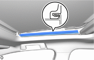
6. REMOVE NO. 2 SLIDING ROOF SIDE GARNISH RH
| (a) Detach the claw and remove the No. 2 sliding roof side garnish RH. |
|
7. REMOVE NO. 2 SLIDING ROOF SIDE GARNISH LH
HINT:
Use the same procedure as for the RH side.
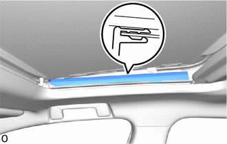
8. REMOVE NO. 1 SLIDING ROOF SIDE GARNISH RH
| (a) Detach the claw and remove the No. 1 sliding roof side garnish RH. |
|
9. REMOVE NO. 1 SLIDING ROOF SIDE GARNISH LH
HINT:
Use the same procedure as for the RH side.
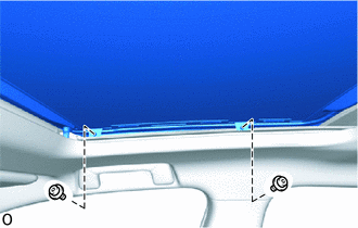
10. REMOVE SLIDING ROOF GLASS SUB-ASSEMBLY
| (a) Using a T25 "TORX" socket wrench, remove the 4 screws and sliding roof panel sub-assembly. NOTICE: To prevent the sliding roof glass and sliding roof drive gear from being displaced, fully close the sliding roof glass (sliding roof drive cable), and then remove the sliding roof drive gear. HINT: The illustration shows the RH side. The vertical orientation of the LH side is opposite that of the image shown in the illustration. |
|
11. REMOVE SLIDING ROOF WEATHERSTRIP
(a) Remove the sliding roof weatherstrip from the sliding roof panel sub-assembly.
12. REMOVE CURTAIN SHIELD AIRBAG ASSEMBLY LH
Click here
13. REMOVE CURTAIN SHIELD AIRBAG ASSEMBLY RH
HINT:
Use the same procedure described for the LH side.
14. REMOVE REAR SIDE RAIL SPACER LH
Click here
15. REMOVE REAR SIDE RAIL SPACER RH
HINT:
Use the same procedure described for the LH side.
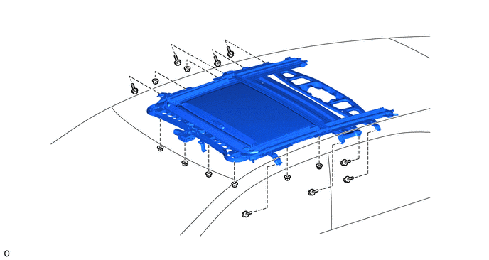
16. REMOVE SLIDING ROOF HOUSING SUB-ASSEMBLY
(a) Detach the 4 sliding roof drain hose clamps.
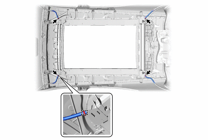
(b) Disconnect the 4 sliding roof drain hoses.
(c) Remove the 8 bolts, 8 nuts and sliding roof housing sub-assembly.
READ NEXT:
 Reassembly
REASSEMBLY PROCEDURE 1. INSTALL ROOF WIND DEFLECTOR PANEL SUB-ASSEMBLY (a) Attach the 2 guides as shown in the illustration to install the roof wind deflector panel sub-assembly. (b) Attach the 2 spr
Installation
INSTALLATION PROCEDURE 1. INSTALL SLIDING ROOF HOUSING SUB-ASSEMBLY (a) Temporarily install the sliding roof housing sub-assembly with the 8 bolts and 8 nuts. (b) Tighten the nuts in the order indica
Sliding Roof Switch Assembly
ComponentsCOMPONENTS ILLUSTRATION *1 MAP LIGHT ASSEMBLY (SLIDING ROOF SWITCH ASSEMBLY) - - InspectionINSPECTION PROCEDURE 1. INSPECT MAP LIGHT ASSEMBLY (SLIDING ROOF SWITCH ASSEMBLY)
SEE MORE:
Right Headlight ECU Malfunction (B242C,B242D)
DESCRIPTION These DTCs are output when an internal malfunction in the headlight ECU sub-assembly occurs. The headlight ECU sub-assembly LH outputs DTC B242C and B242D. DTC No. Detection Item DTC Detection Condition Trouble Area B242C Right Headlight ECU Malfunction Headlight ECU sub
Vehicle Information Unmatched (C168D)
DESCRIPTION This DTC is stored if the rear television camera assembly judges as a result of its self check that the vehicle information received from the main body ECU (multiplex network body ECU) via CAN communication and the vehicle information stored in the television camera assembly do not match
