Lexus NX: Installation
INSTALLATION
PROCEDURE
1. INSTALL SLIDING ROOF HOUSING SUB-ASSEMBLY
(a) Temporarily install the sliding roof housing sub-assembly with the 8 bolts and 8 nuts.
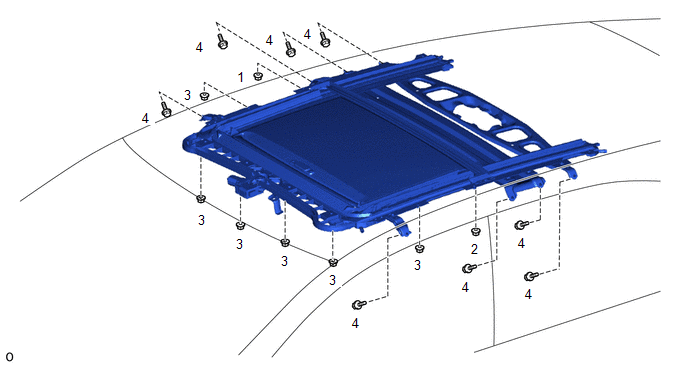
(b) Tighten the nuts in the order indicated in the illustration.
Torque:
8.0 N·m {82 kgf·cm, 71 in·lbf}
(c) Insert the sliding roof drain hose.
NOTICE:
Make sure the sliding roof drain hose is securely inserted to prevent water leakage.
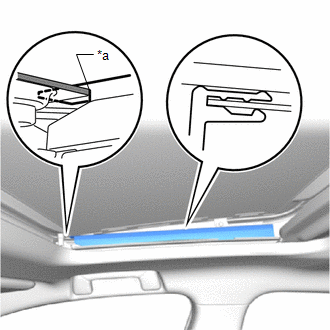
(d) Attach the claw to install the front sliding roof drain hose clamps as shown in the illustration.
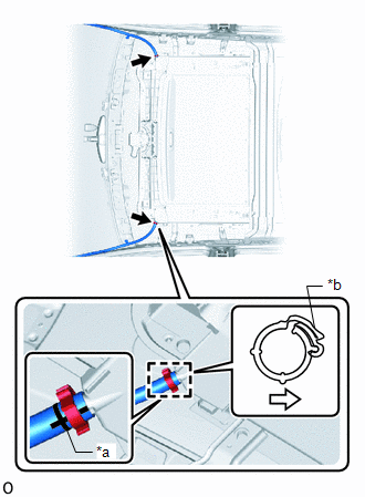
| *a | Marking |
| *b | Lock Portion of Clip |
.png) | Rear of Vehicle |
NOTICE:
- Install the clip on the sliding roof housing sub-assembly side of the marking.
- Make sure that the lock portion of the clip is facing the rear of the vehicle.
- Make sure that the marking on the sliding roof drain hose is facing the bottom of the vehicle.
HINT:
Use the same procedure for both front sliding roof drain hose clamps.
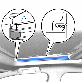
(e) Attach the claw to install the rear sliding roof drain hose clamps as shown in the illustration.
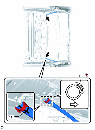
| *a | Marking |
| *b | Lock Portion of Clip |
| | Inside of Vehicle |
NOTICE:
- Install the clip on the sliding roof housing sub-assembly side of the marking.
- Make sure that the lock portion of the clip is facing toward the inside of the vehicle.
- Make sure that the marking on the sliding roof drain hose is facing the bottom of the vehicle.
HINT:
Use the same procedure for both rear sliding roof drain hose clamps.
2. INSTALL REAR SIDE RAIL SPACER LH
Click here .gif)
3. INSTALL REAR SIDE RAIL SPACER RH
HINT:
Use the same procedure described for the LH side.
4. INSTALL SLIDING ROOF WEATHERSTRIP
(a) Install the sliding roof weatherstrip as follows:
(1) Align the marks on the sliding roof weatherstrip with the outside marks at the corners of the sliding roof panel sub-assembly and install the sliding roof weatherstrip.
HINT:
After installing, the sliding roof weatherstrip marking must be within the range between the inside and outside markings at each of the corners.
(2) Install the lip of the sliding roof weatherstrip firmly.
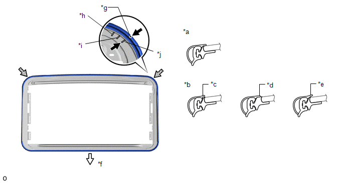
| *a | Normal | *b | Abnormal |
| *c | Pinched | *d | Exposed |
| *e | Gap (raised, wavy, etc.) | *f | Vehicle Rear |
| *g | Alignment Mark | *h | Inside Mark |
| *i | Middle Mark | *j | Outside Mark |
5. INSTALL SLIDING ROOF GLASS SUB-ASSEMBLY
(a) Using a T25 "TORX" socket wrench, temporarily install the sliding roof glass sub-assembly with the 4 screws.
(b) Perform a level check.
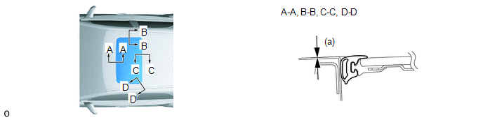
(1) Check the difference in level for "a" between the roof panel and the upper surface of the weatherstrip when the sliding roof glass is fully closed.
Standard:
| Area | Measurement |
|---|---|
| A - A | 0 + 1.0 mm (0 + 0.0394 in.) 0 - 1.0 mm (0 - 0.0394 in.) |
| B - B | 0 + 1.0 mm (0 + 0.0394 in.) 0 - 1.0 mm (0 - 0.0394 in.) |
| C - C | 0 + 1.0 mm (0 + 0.0394 in.) 0 - 1.0 mm (0 - 0.0394 in.) |
| D - D | 0 + 1.0 mm (0 + 0.0394 in.) 0 - 1.0 mm (0 - 0.0394 in.) |
HINT:
"+" represents the condition that the glass is above the panel level. "-" represents the condition that the glass is below the panel level.
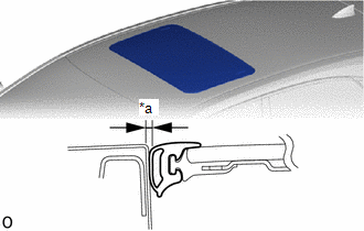
| (c) Perform a gap check. (1) Check the gap between the roof panel and roof glass. NOTICE: The gap must be even all around. |
|
(d) After adjusting the sliding roof glass, using a T25 "TORX" socket wrench, install the sliding roof glass sub-assembly with the 4 screws.
Torque:
4.0 N·m {41 kgf·cm, 35 in·lbf}
6. CHECK FOR WATER LEAK
(a) After adjusting the sliding roof glass sub-assembly, check for water leakage into the vehicle interior.
(b) If there are any leaks, readjust the sliding roof glass sub-assembly.
7. INSTALL CURTAIN SHIELD AIRBAG ASSEMBLY LH
Click here
8. INSTALL CURTAIN SHIELD AIRBAG ASSEMBLY RH
HINT:
Use the same procedure described for the LH side.
9. INSTALL NO. 1 SLIDING ROOF SIDE GARNISH RH
(a) Attach the claw to install the No. 1 sliding roof side garnish RH.
| *a | Edge of the No. 1 Sliding Roof Side Garnish RH |
.png) | Installation Reference Surface. |
HINT:
Align the edge of the No. 1 sliding roof side garnish RH with the installation reference surface.
10. INSTALL NO. 1 SLIDING ROOF SIDE GARNISH LH
HINT:
Use the same procedure described for the RH side.
11. INSTALL NO. 2 SLIDING ROOF SIDE GARNISH RH
(a) Attach the claw to install the No. 2 sliding roof side garnish RH.
| *a | Edge of the No. 2 Sliding Roof Side Garnish RH |
| | Installation Reference Surface. |
HINT:
Align the edge of the No. 2 sliding roof side garnish RH with the installation reference surface.
12. INSTALL NO. 2 SLIDING ROOF SIDE GARNISH LH
HINT:
Use the same procedure described for the RH side.
13. CONNECT CABLE TO NEGATIVE AUXILIARY BATTERY TERMINAL
14. INITIALIZATION AFTER RECONNECTING AUXILIARY BATTERY TERMINAL
Click here
HINT:
When disconnecting and reconnecting the auxiliary battery, there is an automatic learning function that completes learning when the respective system is used.
Click here
15. RESET SLIDING ROOF DRIVE GEAR SUB-ASSEMBLY
Click here
16. CHECK SLIDING ROOF SYSTEM
Click here
17. CHECK SRS WARNING LIGHT
Click here
18. INSTALL DECK FLOOR BOX LH
Click here
19. INSTALL REAR DECK FLOOR BOX
Click here
20. INSTALL NO. 3 DECK BOARD SUB-ASSEMBLY
Click here
READ NEXT:
 Sliding Roof Switch Assembly
ComponentsCOMPONENTS ILLUSTRATION *1 MAP LIGHT ASSEMBLY (SLIDING ROOF SWITCH ASSEMBLY) - - InspectionINSPECTION PROCEDURE 1. INSPECT MAP LIGHT ASSEMBLY (SLIDING ROOF SWITCH ASSEMBLY)
Parts Location
PARTS LOCATION ILLUSTRATION *1 FRONT DOOR COURTESY LIGHT SWITCH ASSEMBLY LH *2 MAP LIGHT ASSEMBLY *3 SLIDE ROOF SWITCH *4 SLIDING ROOF DRIVE GEAR SUB-ASSEMBLY
- SLIDING ROOF ECU
SEE MORE:
Throttle Actuator Control Throttle Body Range / Performance (P2119)
DESCRIPTION The electronic throttle control system is composed of the throttle actuator, throttle position sensor, and ECM. The ECM operates the throttle actuator to regulate the throttle valve in response to a request from the hybrid system. The throttle position sensor detects the opening angle of
Sub Radiator
RemovalREMOVAL PROCEDURE 1. REMOVE NO. 1 ENGINE UNDER COVER ASSEMBLY Click here 2. DRAIN COOLANT (for Inverter Coolant) Click here 3. REMOVE UPPER RADIATOR SUPPORT SUB-ASSEMBLY Click here 4. REMOVE NO. 2 FAN SHROUD Click here 5. REMOVE RADIATOR ASSEMBLY (for Inverter Coolant) (a) Slide
