Lexus NX: Sliding Roof Switch Assembly
Components
COMPONENTS
ILLUSTRATION
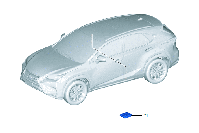
| *1 | MAP LIGHT ASSEMBLY (SLIDING ROOF SWITCH ASSEMBLY) | - | - |
Inspection
INSPECTION
PROCEDURE
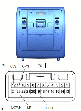
1. INSPECT MAP LIGHT ASSEMBLY (SLIDING ROOF SWITCH ASSEMBLY)
| (a) Measure the resistance according to the value(s) in the table below. Standard Resistance:
If the result is not as specified, replace the map light assembly (sliding roof switch assembly). |
|
Removal
REMOVAL
PROCEDURE
1. REMOVE MAP LIGHT ASSEMBLY (SLIDING ROOF SWITCH ASSEMBLY)
Click here .gif)
Installation
INSTALLATION
PROCEDURE
1. INSTALL MAP LIGHT ASSEMBLY (SLIDING ROOF SWITCH ASSEMBLY)
Click here .gif)
READ NEXT:
 Parts Location
PARTS LOCATION ILLUSTRATION *1 FRONT DOOR COURTESY LIGHT SWITCH ASSEMBLY LH *2 MAP LIGHT ASSEMBLY *3 SLIDE ROOF SWITCH *4 SLIDING ROOF DRIVE GEAR SUB-ASSEMBLY
- SLIDING ROOF ECU
System Diagram
SYSTEM DIAGRAM
SEE MORE:
ACC Monitor Malfunction (B2274)
DESCRIPTION This DTC is stored when a malfunction in the ACC output circuit is detected. The ACC output circuit is the circuit that goes from the ACC output terminal of the certification ECU (smart key ECU assembly) to the ACC relay. DTC No. Detection Item DTC Detection Condition Trouble Ar
Inspection
INSPECTION PROCEDURE 1. INSPECT FUEL INJECTOR ASSEMBLY (a) Measure the resistance according to the value(s) in the table below. Standard Resistance: Tester Connection Condition Specified Condition 1 - 2 20°C (68°F) 11.6 to 12.4 Ω If the result is not as specified, replace the f
