Lexus NX: Components
Lexus NX Service Manual / Vehicle Exterior / Mirror (ext) / Outer Rear View Mirror Glass / Components
COMPONENTS
ILLUSTRATION
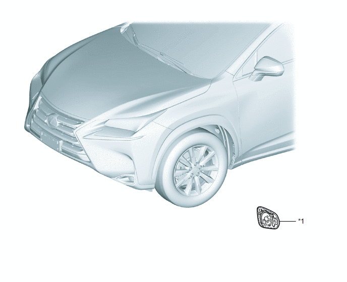
| *1 | OUTER MIRROR LH | - | - |
READ NEXT:
 Removal
REMOVAL CAUTION / NOTICE / HINT HINT:
Use the same procedure for the RH and LH sides.
The procedure listed below is for the LH side.
PROCEDURE 1. REMOVE OUTER MIRROR LH (a) Push the upper part
Inspection
INSPECTION PROCEDURE 1. INSPECT OUTER MIRROR LH (a) Check the outer mirror heater operation. (1) Measure the resistance according to the value(s) in the table below. Standard Resistance: Tester
Installation
INSTALLATION CAUTION / NOTICE / HINT HINT:
Use the same procedure for the RH and LH sides.
The procedure listed below is for the LH side.
PROCEDURE 1. INSTALL OUTER MIRROR LH (a) w/o EC Mir
SEE MORE:
Problem Symptoms Table
PROBLEM SYMPTOMS TABLE HINT: Use the table below to help determine the cause of problem symptoms. If multiple suspected areas are listed, the potential causes of the symptoms are listed in order of probability in the "Suspected Area" column of the table. Check each symptom by checking the suspected
Removal
REMOVAL PROCEDURE 1. PRECAUTION NOTICE: After turning the power switch is turned off, there may be a waiting time before disconnecting the auxiliary negative (-) battery terminal. Click here 2. CUSTOMIZE POWER TILT AND POWER TELESCOPIC STEERING COLUMN SYSTEM (a) Disable the auto tilt away function
© 2016-2026 Copyright www.lexunx.com
