Lexus NX: Removal
REMOVAL
CAUTION / NOTICE / HINT
HINT:
- Use the same procedure for the RH and LH sides.
- The procedure listed below is for the LH side.
PROCEDURE
1. PRECAUTION
NOTICE:
After the power switch is turned off, there may be a waiting time before disconnecting the negative (-) auxiliary battery terminal.
Click here .gif)
2. REMOVE NO. 3 DECK BOARD SUB-ASSEMBLY
Click here
3. REMOVE REAR DECK FLOOR BOX
Click here
4. REMOVE DECK FLOOR BOX LH
Click here
5. DISCONNECT CABLE FROM NEGATIVE AUXILIARY BATTERY TERMINAL
CAUTION:
Wait at least 90 seconds after disconnecting the cable from the negative (-) battery terminal to disable the SRS system.
6. REMOVE REAR POWER WINDOW REGULATOR SWITCH ASSEMBLY WITH REAR DOOR ARMREST BASE PANEL
Click here
7. REMOVE REAR DOOR INSIDE HANDLE BEZEL PLUG LH
Click here
8. REMOVE REAR DOOR TRIM COVER LH
Click here
9. REMOVE REAR DOOR TRIM BOARD SUB-ASSEMBLY LH
Click here
10. REMOVE REAR DOOR ARMREST SET BRACKET LH
Click here
11. REMOVE REAR DOOR SERVICE HOLE COVER LH
Click here
12. REMOVE REAR DOOR GLASS RUN LH
Click here
13. REMOVE REAR LOWER REAR DOOR WINDOW FRAME SUB-ASSEMBLY LH
Click here
14. REMOVE REAR DOOR REAR GUIDE SEAL LH
Click here
15. REMOVE REAR DOOR GLASS SUB-ASSEMBLY LH
Click here
16. REMOVE REAR DOOR WINDOW REGULATOR SUB-ASSEMBLY LH
Click here
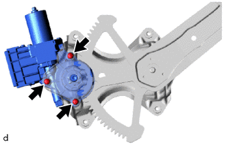
17. REMOVE POWER WINDOW REGULATOR MOTOR ASSEMBLY LH
| (a) Using a T25 "TORX" socket wrench, remove the 3 "TORX" screws and power window regulator motor assembly LH. |
|
READ NEXT:
 Inspection
INSPECTION PROCEDURE 1. INSPECT POWER WINDOW REGULATOR MOTOR ASSEMBLY LH NOTICE:
Do not apply voltage to any terminals except terminals 1 and 2 to avoid damaging the pulse sensor inside the motor.
Installation
INSTALLATION CAUTION / NOTICE / HINT HINT:
Use the same procedure for the RH and LH sides.
The procedure listed below is for the LH side.
A bolt without a torque specification is shown in the s
SEE MORE:
Drive Belt
ComponentsCOMPONENTS ILLUSTRATION *1 FAN AND GENERATOR V BELT *2 REAR ENGINE UNDER COVER RH On-vehicle InspectionON-VEHICLE INSPECTION PROCEDURE 1. INSPECT FAN AND GENERATOR V BELT (a) Check the fan and generator V belt for wear, cracks or other signs of damage. If any of the follo
On-vehicle Inspection
ON-VEHICLE INSPECTION CAUTION / NOTICE / HINT CAUTION: Be sure to follow the correct removal and installation procedures of the front airbag sensors. PROCEDURE 1. INSPECT FRONT AIRBAG SENSOR (for Vehicle not Involved in Collision) (a) Perform a diagnostic system check. Click here 2. INSPECT FRONT
