Lexus NX: Operation Check
OPERATION CHECK
HINT:
The blind spot monitor beam axis confirmation is performed to confirm whether the sensor's beam axis is correct, and perform adjustment of the beam axis by using reflector.
BLIND SPOT MONITOR BEAM AXIS CONFIRMATION
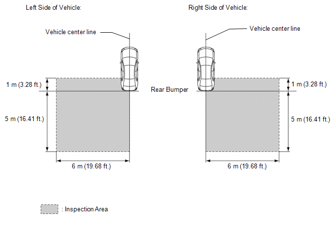
(a) When performing the blind spot monitor beam axis confirmation, move the vehicle to a place where the space shown in the illustration can be secured.
NOTICE:
- Perform this inspection on level ground.
- Make sure that there are no metal objects around the vehicle or on the ground.
- Unload the vehicle before beginning the inspection.
- Confirm that the tire pressure is correct before beginning the inspection.
- Do not place any objects other than the reflector (such as a large metallic object) in or allow people to enter the inspection area (W 6 m [19.68 ft.] x L 6 m [19.68 ft.] x H 4 m [13.12 ft.]) shown in the illustration.
(b) Place the reflector.
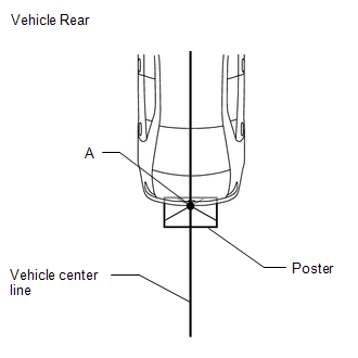
(1) From the center of the rear bumper (center of the emblem), hang a weight with a pointed tip, and mark the rear center point of the vehicle on the ground (mark A).
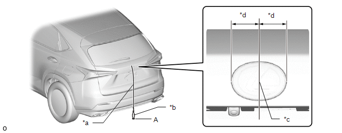
| *a | String | *b | Weight |
| *c | Center point | *d | Equal Distance to Center |
HINT:
Lightly flick the string with your fingers several times to confirm that the string is aligned with mark A.
(2) From the center of the front bumper (center of the emblem), hang a weight with a pointed tip, and mark the front center point of the vehicle on the ground (mark B).
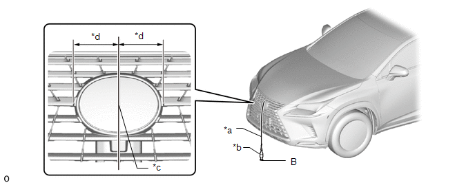
| *a | String | *b | Weight |
| *c | Center point | *d | Equal Distance to Center |
HINT:
Lightly flick the string with your fingers several times to confirm that the string is aligned with mark B.
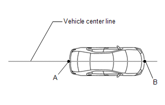
(3) Draw a vehicle center line so that it passes through mark A and B (front and rear center points).
(4) Enlarge and print out the poster shown in the illustration.
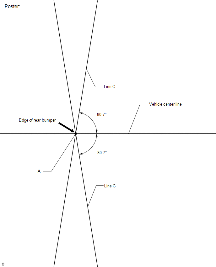
(5) Attach the printed poster to the floor with the vehicle center line aligned with point A as shown in the illustration.
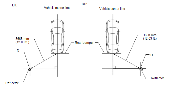
(6) Align a piece of string with line C and mark point D at a distance of 3668 mm (12.03 ft.) from point A.
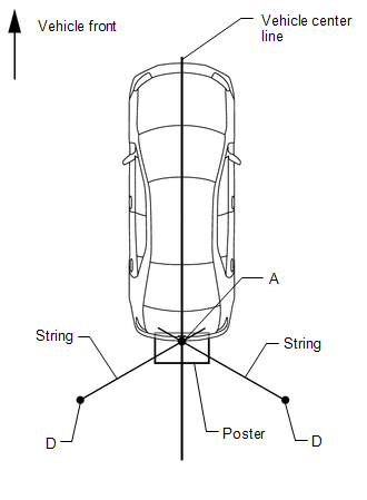
(7) Set the reflector at the point D shown in the illustration below.
SST: 09870-60000
09870-60010
SST: 09870-60040
NOTICE:
-
Set the reflector so that its center is 790 mm (2.59 ft.) above the ground.
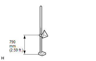
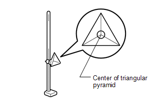
-
The center of the triangular pyramid is the reference point for the setting position and angle.
(c) Perform the blind spot monitor beam axis display.
(1) Connect the Techstream to the DLC3.
(2) Turn the power switch on (IG).
(3) Turn the blind spot monitor system on.
(4) Turn the Techstream on.
(5) Enter the following menus: Body Electrical / Blind Spot Monitor Master or Blind Spot Monitor Slave / Utility / BSM Master Beam Axis Display or BSM Slave Beam Axis Display.
Body Electrical > Blind Spot Monitor Master > Utility| Tester Display |
|---|
| BSM Master Beam Axis Display |
| Tester Display |
|---|
| BSM Slave Beam Axis Display |
(6) Check the results displayed for the BSM beam axis display.
Allowable Range:
| Item | Blind Spot Monitor Sensor LH (Master) | Blind Spot Monitor Sensor RH (Slave) |
|---|---|---|
| Angle | -3.6 to +3.6° | -3.6 to +3.6° |
HINT:
If the results are outside the allowable range, it is possible that the reflector position is incorrect, there is a metallic object near the inspection area or the blind spot monitor sensor installation condition is abnormal, so check the reflector positioning, the inspection area and the blind spot monitor sensor installation condition, and perform the inspection again.
(d) Perform the blind spot monitor beam axis adjustment.
(1) Enter the following menus: Body Electrical / Blind Spot Monitor Master or Blind Spot Monitor Slave / Utility / BSM Master Beam Axis Adjustment or BSM Slave Beam Axis Adjustment.
HINT:
When values on the axis display are in the allowable range, performing this adjustment compensates for any deviation from the normal value.
Body Electrical > Blind Spot Monitor Master > Utility| Tester Display |
|---|
| BSM Master Beam Axis Adjustment |
| Tester Display |
|---|
| BSM Slave Beam Axis Adjustment |
BLIND SPOT MONITOR SENSOR INSTALLATION CONDITION INSPECTION
NOTICE:
- Perform this inspection on level ground.
- Unload the vehicle before beginning the inspection.
- Confirm that the tire pressure is correct before beginning the inspection.
HINT:
The blind spot monitor sensor installation condition inspection is performed to confirm whether the sensor is perpendicular to the floor surface (+/-2.2°) by using a digital angle gauge, and that the sensor is 16 to 24° from the line parallel to the vehicle center line.
(a) Remove the rear bumper.
Click here .gif)
(b) Place the digital angle gauge on a level (gradient within 1%) and perform zero-point adjustment as shown in the illustration.
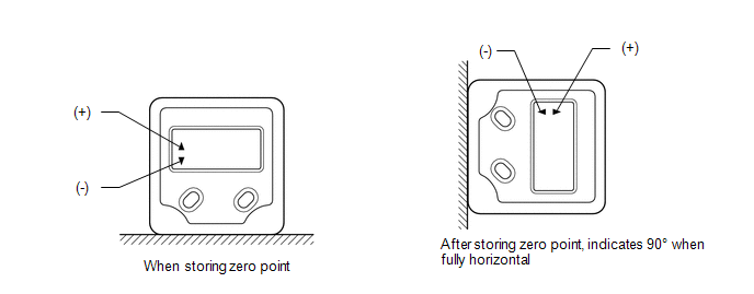
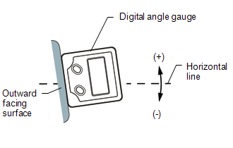
(c) Set the digital angle gauge to the outward facing surface of the blind spot monitor sensor as shown in the illustration, and check that the perpendicular angle of the blind spot monitor sensor is within the permissible range.
HINT:
The outward facing surface (installation angle) is positive (+) when it faces higher than horizontal.
Standard:
| Item | Allowable Range |
|---|---|
| Blind Spot Monitor Sensor LH (Master) | +87.8 to +92.2° |
| Blind Spot Monitor Sensor RH (Slave) | +87.8 to +92.2° |
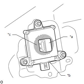
| *a | Digital Angle Gauge |
| *b | Blind Spot Monitor Sensor |
| *c | Outward Facing Surface |
(d) Using the sensor installation stud bolt center lines as a reference, check that the stud bolts are as shown in the illustration.
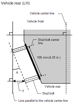
Standard:
| Dimension | Specified Value |
|---|---|
| y | 29 to 44 mm (1.14 to 1.73 in.) |
| Degree | Specified Value |
|---|---|
| A | 16 to 24° |
HINT:
If the results are not as specified, it is possible that the blind spot monitor sensor installation area (frame, stud bolt) is deformed, so make corrections as necessary.
READ NEXT:
 Problem Symptoms Table
PROBLEM SYMPTOMS TABLE NOTICE: When replacing the combination meter assembly, always replace it with a new one. If a combination meter assembly which was installed to another vehicle is used, the info
Terminals Of Ecu
TERMINALS OF ECU BLIND SPOT MONITOR SENSOR LH (MASTER) Terminal No. (Symbol) Wiring Color Terminal Description Condition Specified Condition V1-3 (BIND) - V1-10 (BLGD) B - W-B Blin
Diagnosis System
DIAGNOSIS SYSTEM DESCRIPTION (a) Blind spot monitor data and Diagnostic Trouble Codes (DTCs) can be read from the Data Link Connector 3 (DLC3) of the vehicle. When the system seems to be malfunctionin
SEE MORE:
Parking Brake System
PrecautionPRECAUTION CAUTION: Perform each part replacement carefully, as mistakes could affect the brake system performance and lead to driving problems. When replacing a part, replace with the same part or equivalent. NOTICE:
As these procedures may affect the SRS airbags, it is necessary to r
Sub Radiator
RemovalREMOVAL PROCEDURE 1. REMOVE NO. 1 ENGINE UNDER COVER ASSEMBLY Click here 2. DRAIN COOLANT (for Inverter Coolant) Click here 3. REMOVE UPPER RADIATOR SUPPORT SUB-ASSEMBLY Click here 4. REMOVE NO. 2 FAN SHROUD Click here 5. REMOVE RADIATOR ASSEMBLY (for Inverter Coolant) (a) Slide
