Lexus NX: Removal
REMOVAL
PROCEDURE
1. REMOVE BACK DOOR CENTER GARNISH
Click here .gif)
2. REMOVE BACK DOOR SIDE GARNISH LH
Click here
3. REMOVE BACK DOOR SIDE GARNISH RH
Click here
4. REMOVE BACK DOOR TRIM BASE (w/ Power Back Door)
Click here
5. REMOVE PULL HANDLE (w/ Power Back Door)
Click here
6. REMOVE BACK DOOR FINISH COVER LH (w/o Power Back Door)
Click here
7. REMOVE BACK DOOR FINISH COVER RH (w/o Power Back Door)
Click here
8. REMOVE BACK DOOR LOCK COVER (w/ Power Back Door)
Click here
9. REMOVE BACK DOOR LOCK COVER (w/o Power Back Door)
Click here
10. REMOVE BACK DOOR TRIM BOARD ASSEMBLY
Click here
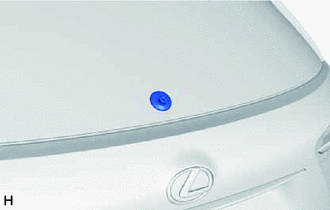
11. REMOVE REAR WIPER ARM HEAD CAP
| (a) Detach the 2 claws and open the rear wiper arm head cap as shown in the illustration. |
|
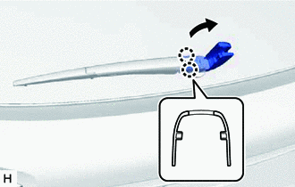
| (b) Detach the 2 claws and remove the rear wiper arm head cap. |
|
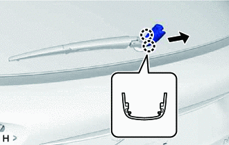
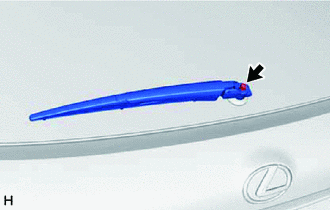
12. REMOVE REAR WIPER ARM AND BLADE ASSEMBLY
| (a) Remove the nut and the rear wiper arm and blade assembly. |
|
13. REMOVE REAR WIPER MOTOR ASSEMBLY
| (a) Disconnect the connector. |
|
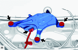
(b) Loosen the 3 bolts and rear wiper motor assembly.
14. REMOVE REAR WIPER MOTOR GROMMET
| (a) Remove the rear wiper motor grommet. |
|
READ NEXT:
 Inspection
INSPECTION PROCEDURE 1. INSPECT REAR WIPER MOTOR ASSEMBLY *a Component without harness connected (Rear Wiper Motor Assembly) (a) Check that the rear wiper motor assembly operates. NOTICE: Che
Installation
INSTALLATION PROCEDURE 1. INSTALL REAR WIPER MOTOR GROMMET (a) Apply MP grease to the entire circumference of the lip portion of the rear wiper motor grommet. HINT: Do not fill the hole with MP gre
Rear Wiper Rubber
ComponentsCOMPONENTS ILLUSTRATION *1 REAR WIPER BLADE *2 REAR WIPER RUBBER *3 REAR WIPER BACKING PLATE - - ReplacementREPLACEMENT PROCEDURE 1. REMOVE REAR WIPER BLADE (a) Move
SEE MORE:
Reassembly
REASSEMBLY CAUTION / NOTICE / HINT CAUTION: Wear protective gloves. Sharp areas on the parts may injure your hands. PROCEDURE 1. INSTALL REAR SEAT WIRE LH (for LH Side) (a) Attach the 2 clamps to install the rear seat wire LH. (b) Connect the 2 connectors. 2. INSTALL FOLD SEAT CONTROL
System Description
SYSTEM DESCRIPTION AUTOMATIC LIGHT CONTROL SYSTEM (a) When the headlight dimmer switch is in the AUTO position, the automatic light control system detects ambient light levels and controls the headlights, taillights, front fog lights, clearance lights and license plate lights. LIGHT AUTO TURN-OFF SY
