Lexus NX: Removal
REMOVAL
PROCEDURE
1. PRECAUTION
NOTICE:
After turning the power switch off, waiting time may be required before disconnecting the cable from the negative (-) auxiliary battery terminal.
Click here .gif)
2. REMOVE DECK BOARD ASSEMBLY
Click here
3. REMOVE NO. 3 DECK BOARD SUB-ASSEMBLY
Click here
4. REMOVE REAR DECK FLOOR BOX
Click here
5. REMOVE DECK FLOOR BOX LH
Click here
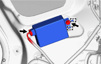
6. DISCONNECT CABLE FROM NEGATIVE AUXILIARY BATTERY TERMINAL
CAUTION:
Wait at least 90 seconds after disconnecting the cable from the negative (-) battery terminal to disable the SRS system.
7. REMOVE REAR SEAT ASSEMBLY
-
for Manual Seat:
Click here
-
for Power Seat:
Click here
8. REMOVE TONNEAU COVER ASSEMBLY
Click here
9. REMOVE NO. 2 DECK BOARD SUB-ASSEMBLY
Click here
10. REMOVE DECK FLOOR BOX RH
Click here
11. REMOVE NO. 1 TOOL BOX SUB-ASSEMBLY
Click here
12. REMOVE NO. 2 TOOL BOX SUB-ASSEMBLY
Click here
13. REMOVE REAR FLOOR FINISH PLATE
Click here
14. REMOVE BATTERY SERVICE COVER BOARD
-
for Manual Seat:
Click here
-
for Power Seat:
Click here
15. REMOVE NO. 1 SEAT LEG ASSEMBLY
-
for Manual Seat:
Click here
-
for Power Seat:
Click here
16. REMOVE REAR DOOR OPENING TRIM WEATHERSTRIP RH
Click here
17. REMOVE ROPE HOOK ASSEMBLY
Click here
18. REMOVE LUGGAGE HOLD BELT STRIKER ASSEMBLY
Click here
19. REMOVE NO. 1 LUGGAGE COMPARTMENT TRIM HOOK
Click here
20. REMOVE UPPER DECK TRIM SIDE BOARD RH
Click here
21. REMOVE DECK TRIM SIDE PANEL ASSEMBLY RH
Click here
22. REMOVE INNER ROOF SIDE GARNISH ASSEMBLY RH
Click here
23. REMOVE ELECTRICAL KEY AND TPMS RECEIVER ASSEMBLY
(a) Remove the bolt.
(b) Detach the 2 guides and remove the ectrical key and TPMS receiver assembly.
| (c) Disconnect the connector. |
|
READ NEXT:
 Installation
INSTALLATION CAUTION / NOTICE / HINT HINT: A bolt without a torque specification is shown in the standard bolt chart. Click here PROCEDURE 1. INSTALL ELECTRICAL KEY AND TPMS RECEIVER ASSEMBLY (a) Co
Door Control Switch
ComponentsCOMPONENTS ILLUSTRATION *1 DOOR CONTROL SWITCH ASSEMBLY *2 POWER WINDOW REGULATOR SWITCH ASSEMBLY WITH FRONT DOOR ARMREST BASE PANEL *3 FRONT DOOR ARMREST BASE PANEL - -
SEE MORE:
Terminals Of Ecu
TERMINALS OF ECU CHECK HEADLIGHT ECU SUB-ASSEMBLY LH (a) Disconnect the A19 headlight sub-assembly LH connector. (b) Measure the resistance and voltage according to the value(s) in the table below. Terminal No. (Symbol) Wiring Color Terminal Description Condition Specified Condition
Inspection
INSPECTION PROCEDURE 1. INSPECT FUEL PUMP ASSEMBLY WITH FILTER (a) Check the resistance. (1) Measure the resistance according to the value(s) in the table below. Standard Resistance: Tester Connection Condition Specified Condition 1 - 2 20°C (68°F) 0.2 to 3.0 Ω If the result
