Lexus NX: Removal
REMOVAL
PROCEDURE
1. PRECAUTION
CAUTION:
Be sure to read Precaution thoroughly before serving.
Click here .gif)
NOTICE:
After turning the power switch off, there may be a waiting time before disconnecting the negative (-) auxiliary battery terminal.
Click here
2. DISCONNECT CABLE FROM NEGATIVE AUXILIARY BATTERY TERMINAL
CAUTION:
- Wait at least 90 seconds after disconnecting the cable from the negative (-) auxiliary battery terminal to disable the SRS system.
- If the airbag deploys for any reason. it may cause a serious accident.
3. REMOVE UPPER INSTRUMENT PANEL SUB-ASSEMBLY
Click here
4. REMOVE NO. 1 ANTENNA CORD SUB-ASSEMBLY
(a) for Type A:
(1) Disconnect the 2 connectors.
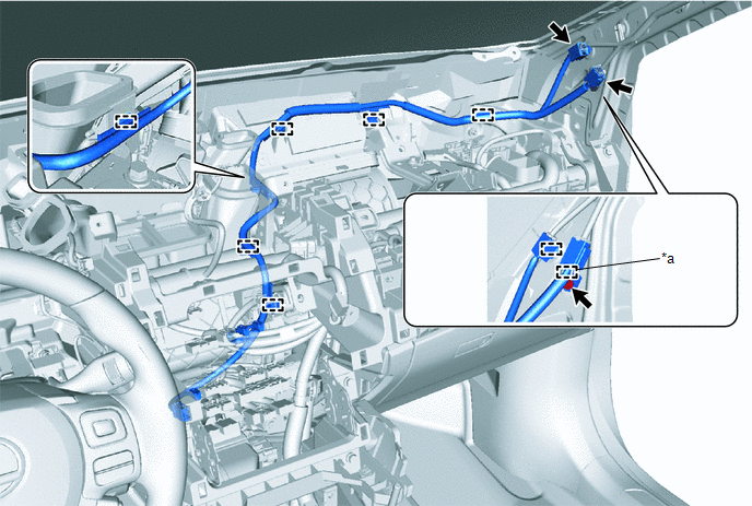
| *a | Guide | - | - |
(2) Remove the bolt.
(3) Detach the 7 clamps, guide and remove the No. 1 antenna cord sub-assembly.
(b) for Type B:
(1) Disconnect the connector.
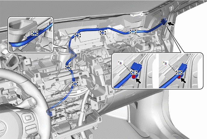
| *a | Guide | - | - |
(2) Remove the bolt.
(3) Detach the 6 clamps, guide and remove the No. 1 antenna cord sub-assembly.
5. REMOVE ROOF HEADLINING ASSEMBLY
Click here
6. REMOVE NO. 2 ANTENNA CORD SUB-ASSEMBLY
(a) Normal roof
(1) Remove the tape enough that the No. 2 antenna cord sub-assembly can be removed, and then remove the No. 2 antenna cord sub-assembly from the double-sided tape on the roof headlining.
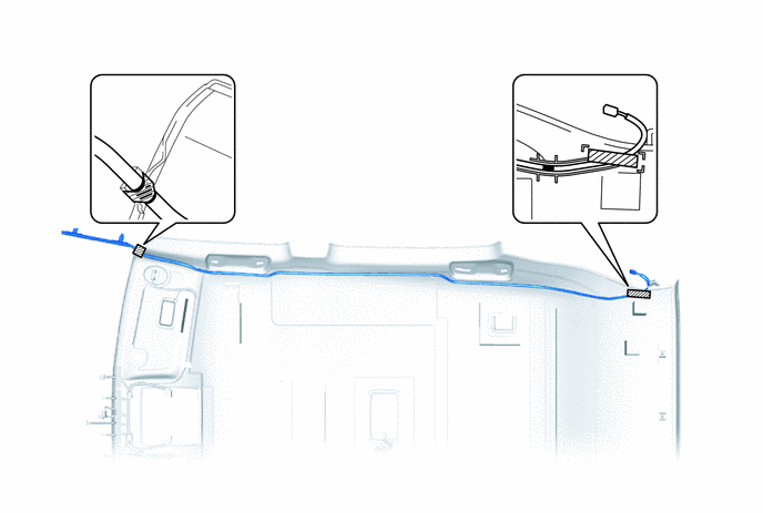
 | Tape | - | - |
(b) Sliding roof
(1) Remove the tape enough that the No. 2 antenna cord sub-assembly can be removed, and then remove the No. 2 antenna cord sub-assembly from the double-sided tape on the roof headlining
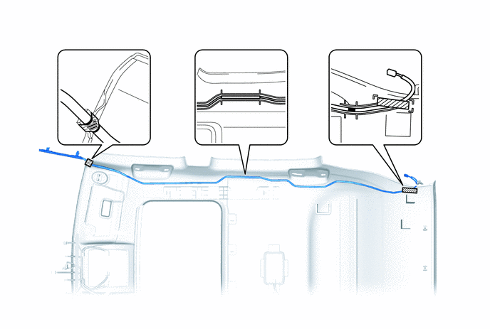
| | Tape | - | - |
7. REMOVE NO. 4 ANTENNA CORD SUB-ASSEMBLY
| (a) Disconnect the 2 connectors. |
|
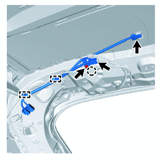
(b) Detach the 2 clamps to washer hose and remove the bolt.
(c) Detach the 2 clamps, guide and remove the No. 4 antenna cord-assembly
READ NEXT:
 Installation
INSTALLATION PROCEDURE 1. INSTALL NO. 4 ANTENNA CORD SUB-ASSEMBLY (a) Attach the 2 clamps and guide to install the No. 4 antenna cord sub-assembly. (b) Install the bolt and attach the 2 clamps to inst
Components
COMPONENTS ILLUSTRATION *1 DECK FLOOR BOX LH *2 NO. 3 DECK BOARD SUB-ASSEMBLY *3 REAR DECK FLOOR BOX *4 NEGATIVE AUXILIARY BATTERY TERMINAL N*m (kgf*cm, ft.*lbf): Specified
SEE MORE:
Portable Player cannot be Connected Manually/Automatically
CAUTION / NOTICE / HINT HINT: Some versions of "Bluetooth" compatible audio players may not function properly, or the functions may be limited using the radio receiver assembly, even if the portable audio player itself can play files. Click here PROCEDURE 1. CHECK CONNECTED DEVICE SETTINGS
Vehicle Control History
VEHICLE CONTROL HISTORY CHECK VEHICLE CONTROL HISTORY HINT: The vehicle control history data stores the history of the reject function and system protection operations.
for Triple Beam Headlight:
Click here
for Single Beam Headlight:
Click here
