Lexus NX: Electrical Key Oscillator(for Rear Floor)
Components
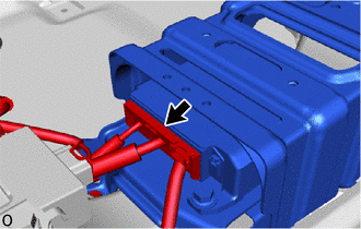
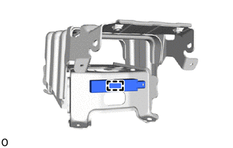
COMPONENTS
ILLUSTRATION
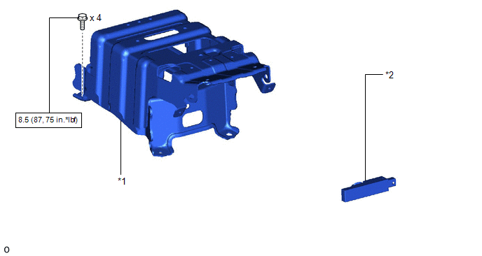
| *1 | NO. 2 CONSOLE BOX MOUNTING BRACKET | *2 | NO. 2 INDOOR ELECTRICAL KEY ANTENNA ASSEMBLY |
.png) | N*m (kgf*cm, ft.*lbf): Specified torque | - | - |
Removal
REMOVAL
PROCEDURE
1. REMOVE REAR CONSOLE BOX ASSEMBLY
Click here .gif)
2. REMOVE NO. 2 CONSOLE BOX MOUNTING BRACKET
| (a) Disconnect the connector. |
|
| (b) Detach the 2 clamps and clip. |
|
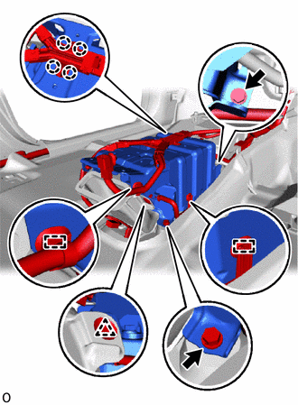
| (c) Detach the 4 claws and remove the 2 bolts. |
|
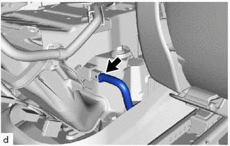
(d) Detach the clamp and clip.
(e) Remove the 2 bolts.
| (f) Disconnect the connector and remove the No. 2 console box mounting bracket. |
|
3. REMOVE NO. 2 INDOOR ELECTRICAL KEY ANTENNA ASSEMBLY
NOTICE:
Do not reuse dropped or damaged parts.
| (a) Detach the clamp and remove the No. 2 indoor electrical key antenna assembly. |
|
Installation
INSTALLATION
PROCEDURE
1. INSTALL NO. 2 INDOOR ELECTRICAL KEY ANTENNA ASSEMBLY
NOTICE:
Do not reuse dropped or damaged parts.
| (a) Attach the clamp to install the No. 2 indoor electrical key antenna assembly. |
|
.png)
2. INSTALL NO. 2 CONSOLE BOX MOUNTING BRACKET
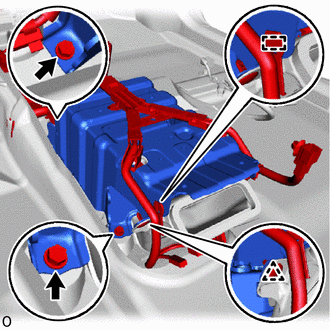
| (a) Temporarily install the No. 2 console box mounting bracket and connect the connector |
|
.png)
| (b) Temporarily install the 2 bolts and attach the clamp and clip. |
|
.png)
| (c) Temporarily install the 2 bolts and attach the 4 claws. |
|
.png)
(d) Attach the 2 clamps and clip.
| (e) Connect the connector and tighten the 4 bolts. Torque: 8.5 N·m {87 kgf·cm, 75 in·lbf} |
|
.png)
3. INSTALL REAR CONSOLE BOX ASSEMBLY
Click here .gif)
READ NEXT:
 Engine Hood Courtesy Switch
ComponentsCOMPONENTS ILLUSTRATION *1 HOOD LOCK ASSEMBLY (ENGINE HOOD COURTESY SWITCH) *2 RADIATOR SUPPORT OPENING COVER N*m (kgf*cm, ft.*lbf) : Specified torque MP grease Re
Id Code Box
ComponentsCOMPONENTS ILLUSTRATION *1 AIR CONDITIONER UNIT ASSEMBLY *2 ID CODE BOX (IMMOBILIZER CODE ECU) InstallationINSTALLATION PROCEDURE 1. INSTALL ID CODE BOX (IMMOBILIZER CODE ECU)
SEE MORE:
Headlight Cleaner Control Relay (for Single Beam Headlight)
ComponentsCOMPONENTS ILLUSTRATION *1 FRONT BUMPER COVER *2 HEADLIGHT CLEANER CONTROL RELAY On-vehicle InspectionON-VEHICLE INSPECTION PROCEDURE 1. INSPECT HEADLIGHT CLEANER CONTROL RELAY (a) Measure the resistance according to the value(s) in the table below. Standard Resistance:
System Description
SYSTEM DESCRIPTION
The power steering system generates torque through the operation of the motor and the reduction gear installed on the column shaft in order to assist steering effort.
The power steering ECU assembly determines the direction and amount of assist power in accordance with vehicl
