Lexus NX: Removal
REMOVAL
PROCEDURE
1. REMOVE NO. 3 DECK BOARD SUB-ASSEMBLY
Click here .gif)
2. REMOVE REAR DECK FLOOR BOX
Click here
3. REMOVE DECK FLOOR BOX LH
Click here
4. PRECAUTION
CAUTION:
Be sure to read Precaution thoroughly before servicing.
Click here
NOTICE:
After the power switch is turned off, there may be a waiting time before disconnecting the negative (-) auxiliary battery terminal.
Click here
5. DISCONNECT CABLE FROM NEGATIVE AUXILIARY BATTERY TERMINAL
CAUTION:
Wait at least 90 seconds after disconnecting the cable from the negative (-) auxiliary battery terminal to disable the SRS system.
(a) Loosen the nut and disconnect the cable from the negative (-) auxiliary battery terminal.
6. REMOVE FRONT CONSOLE BOX
Click here
7. REMOVE AIRBAG ECU ASSEMBLY
(a) Check that the power switch is off.
(b) Check that the cable is disconnected from the negative (-) auxiliary battery terminal.
CAUTION:
Wait at least 90 seconds after disconnecting the cable from the negative (-) auxiliary battery terminal to disable the SRS system.
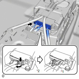
| (c) Disconnect the airbag connector. NOTICE:
(1) Push and pull the connector lock lever to release the connector lock as shown in the illustration. (2) Disconnect the airbag connector. |
|
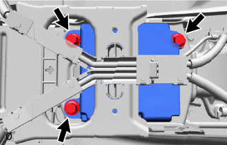
| (d) Remove the 3 bolts and airbag ECU assembly. NOTICE: If the airbag ECU assembly has been dropped, or there are any cracks, dents or other defects in the case or connector, replace the airbag ECU assembly with a new one. |
|
READ NEXT:
 Installation
INSTALLATION PROCEDURE 1. INSTALL AIRBAG ECU ASSEMBLY (a) Check that the power switch is off. (b) Check that the cable is disconnected from the negative (-) auxiliary battery terminal. CAUTION: Wait a
Components
COMPONENTS ILLUSTRATION *1 DECK FLOOR BOX LH *2 NO. 3 DECK BOARD SUB-ASSEMBLY *3 REAR DECK FLOOR BOX *4 AUXILIARY BATTERY NEGATIVE TERMINAL N*m (kgf*cm, ft.*lbf): Specified
SEE MORE:
Evaporative Emission System Leak Detection Reference Orifice Low Flow (P043E,P043F,P2401,P2402,P2419)
DTC SUMMARY DTC No. Detection Item DTC Detection Condition Trouble Area MIL Memory P043E Evaporative Emission System Leak Detection Reference Orifice Low Flow Reference orifice clogged during key-off EVAP monitor
Canister pump module
Connector/wire harness (Canister pump
Drive Motor "A" Phase V Current Sensor Circuit Range / Performance (P0BEA-290,...,P1C6E-502)
DTC SUMMARY MALFUNCTION DESCRIPTION These DTCs indicate the current sensor value is abnormal. The cause of this malfunction may be one of the following: Internal inverter malfunction
Inverter with converter assembly internal circuit malfunction
Inverter low-voltage circuit malfunction
The c
