Lexus NX: Installation
INSTALLATION
PROCEDURE
1. INSTALL AIRBAG ECU ASSEMBLY
(a) Check that the power switch is off.
(b) Check that the cable is disconnected from the negative (-) auxiliary battery terminal.
CAUTION:
Wait at least 90 seconds after disconnecting the cable from the negative (-) auxiliary battery terminal to disable the SRS system.
| (c) Check that the waterproof sheet is properly set. |
|
(d) Install the airbag ECU assembly with the 3 bolts.
Torque:
17.5 N·m {178 kgf·cm, 13 ft·lbf}
NOTICE:
- If the airbag ECU assembly has been dropped, or there are any cracks, dents or other defects in the case or connector, replace the airbag ECU assembly with a new one.
- When installing the airbag ECU assembly, be careful that the SRS wiring does not interfere with or is not pinched between other parts.
- When the power switch is first turned on (READY) after the airbag ECU assembly has been replaced, make sure that no one is in the vehicle.
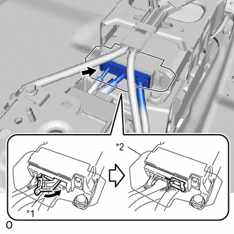
(e) Connect the airbag connector and push the connector lock to lock the airbag connector.
NOTICE:
- When connecting any airbag connector, take care not to damage the airbag wire harness.
- Do not allow the water proof sheet to become pinched.
(f) Check that there is no looseness in the installation parts of the airbag ECU assembly.
2. INSTALL FRONT CONSOLE BOX
Click here .gif)
3. CONNECT CABLE TO NEGATIVE AUXILIARY BATTERY TERMINAL
(a) Connect the cable to the negative (-) auxiliary battery terminal and tighten the nut.
Torque:
5.4 N·m {55 kgf·cm, 48 in·lbf}
4. INITIALIZATION AFTER RECONNECTING AUXILIARY BATTERY TERMINAL
Click here
HINT:
When disconnecting and reconnecting the auxiliary battery, there is an automatic learning function that completes learning when the respective system is used.
Click here
5. INSTALL DECK FLOOR BOX LH
Click here
6. INSTALL REAR DECK FLOOR BOX
Click here
7. INSTALL NO. 3 DECK BOARD SUB-ASSEMBLY
Click here
8. PERFORM DIAGNOSTIC SYSTEM CHECK
Click here
9. CHECK SRS WARNING LIGHT
Click here
READ NEXT:
 Components
COMPONENTS ILLUSTRATION *1 DECK FLOOR BOX LH *2 NO. 3 DECK BOARD SUB-ASSEMBLY *3 REAR DECK FLOOR BOX *4 AUXILIARY BATTERY NEGATIVE TERMINAL N*m (kgf*cm, ft.*lbf): Specified
On-vehicle Inspection
ON-VEHICLE INSPECTION CAUTION / NOTICE / HINT CAUTION: Be sure to follow the correct removal and installation procedures of the curtain shield airbag assemblies. PROCEDURE 1. INSPECT CURTAIN SHIELD AI
SEE MORE:
Fail-safe Chart
FAIL-SAFE CHART HINT: If the power source voltage to the multiplex tilt and telescopic ECU returns to normal within 10 seconds during tilt or telescopic operation, the operation will be resumed. If it returns to normal after 10 seconds have elapsed, the operation restarts when a tilt or telescopic o
Installation
INSTALLATION CAUTION / NOTICE / HINT HINT:
Use the same procedure for the RH and LH sides.
The procedure listed below is for the LH side.
PROCEDURE 1. INSTALL FRONT FENDER MOULDING SUB-ASSEMBLY LH HINT: When installing the front fender moulding sub-assembly LH, heat the vehicle body and fron
