Lexus NX: Removal
REMOVAL
PROCEDURE
1. REMOVE NO. 3 DECK BOARD SUB-ASSEMBLY
Click here .gif)
2. REMOVE REAR DECK FLOOR BOX
Click here
3. REMOVE DECK FLOOR BOX LH
Click here
4. PRECAUTION
CAUTION:
Be sure to read Precaution thoroughly before servicing.
Click here
NOTICE:
After the power switch is turned off, there may be a waiting time before disconnecting the negative (-) auxiliary battery terminal.
Click here
5. DISCONNECT CABLE FROM NEGATIVE AUXILIARY BATTERY TERMINAL
CAUTION:
Wait at least 90 seconds after disconnecting the cable from the negative (-) auxiliary battery terminal to disable the SRS system.
(a) Loosen the nut and disconnect the cable from the negative (-) auxiliary battery terminal.
6. REMOVE DOOR SCUFF PLATE ASSEMBLY LH
Click here
7. REMOVE COWL SIDE TRIM BOARD LH
Click here
8. REMOVE INSTRUMENT SIDE PANEL LH
Click here
9. REMOVE NO. 1 INSTRUMENT PANEL SAFETY PAD SUB-ASSEMBLY
Click here
10. REMOVE REAR CONSOLE ARMREST ASSEMBLY
Click here
11. REMOVE UPPER NO. 2 CONSOLE PANEL GARNISH
Click here
12. REMOVE NO. 1 INSTRUMENT PANEL UNDER COVER SUB-ASSEMBLY
Click here
13. REMOVE LOWER NO. 1 INSTRUMENT PANEL FINISH PANEL
Click here
14. REMOVE LOWER NO. 1 INSTRUMENT PANEL AIRBAG ASSEMBLY
CAUTION:
When storing the lower No. 1 instrument panel airbag assembly, keep the airbag deployment side facing upward.
(a) Check that the power switch is off.
(b) Check that the cable is disconnected from the negative (-) auxiliary battery terminal.
CAUTION:
Wait at least 90 seconds after disconnecting the cable from the negative (-) auxiliary battery terminal to disable the SRS system.
| (c) Remove the 4 bolts. |
|
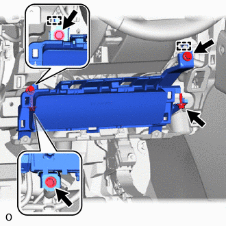
(d) Detach the 2 hooks and remove the lower No. 1 instrument panel airbag assembly.
NOTICE:
When removing the lower No. 1 instrument panel airbag assembly, do not pull the airbag wire harness.
(e) Using a screwdriver, pull up and release the connector lock and disconnect the airbag connector.
NOTICE:
When disconnecting any airbag connector, take care not to damage the airbag wire harness.
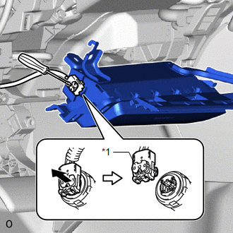
| *1 | Connector Lock |
.png) | Protective Tape |
HINT:
Tape the screwdriver tip before use.
READ NEXT:
 Installation
INSTALLATION CAUTION / NOTICE / HINT HINT:
Use the same procedure for RHD and LHD vehicles.
The procedures listed below are for LHD vehicles.
PROCEDURE 1. INSTALL LOWER NO. 1 INSTRUMENT PANEL
Disposal
DISPOSAL CAUTION / NOTICE / HINT CAUTION: Before performing pre-disposal deployment of any SRS part, review and closely follow all applicable environmental and hazardous material regulations. Pre-disp
SEE MORE:
Forced Release
Operation MethodOPERATION METHOD PROCEDURE 1. PARKING BRAKE FORCED RELEASE NOTICE: Follow the procedures when using SST to release the parking brake. If the parking brake cannot be released, follow the procedures when not using SST. (a) When using SST: (1) Park the vehicle in a safe location, move
Precaution
PRECAUTION HINT:
The following procedures are used to prevent wrinkles from forming when installing the seat cover. Make sure to follow the procedures correctly.
The shape of the seat shown in the illustration may differ from the actual seat.
SEAT COVER SET (a) Align the center cutout of
