Lexus NX: Components
COMPONENTS
ILLUSTRATION
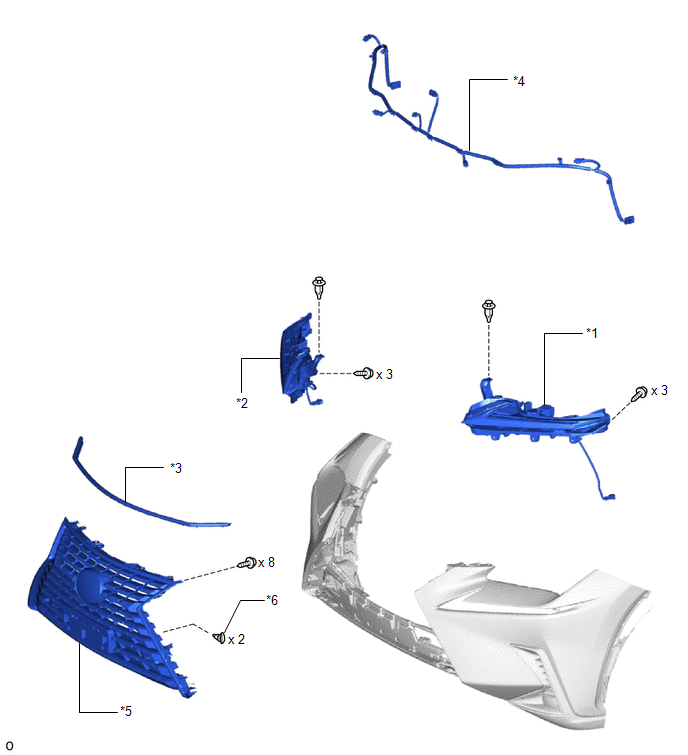
| *1 | CLEARANCE LIGHT ASSEMBLY LH | *2 | CLEARANCE LIGHT ASSEMBLY RH |
| *3 | HOOD TO FRONT END PANEL SEAL | *4 | NO. 3 ENGINE ROOM WIRE |
| *5 | RADIATOR GRILLE SUB-ASSEMBLY | *6 | OUTSIDE MOULDING RETAINER |
ILLUSTRATION
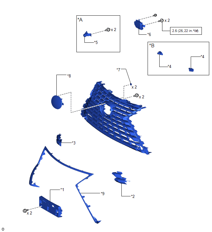
| *A | w/ Panoramic View Monitor System | *B | w/ Intuitive Parking Assist System |
| *1 | FRONT BUMPER EXTENSION MOUNTING BRACKET | *2 | FRONT BUMPER HOLE COVER LH |
| *3 | FRONT BUMPER HOLE COVER RH | *4 | FRONT CENTER ULTRASONIC SENSOR |
| *5 | FRONT TELEVISION CAMERA ASSEMBLY | *6 | MILLIMETER WAVE RADAR SENSOR ASSEMBLY |
| *7 | NUT | *8 | RADIATOR GRILLE EMBLEM |
| *9 | RADIATOR GRILLE MOULDING | - | - |
.png) | N*m (kgf*cm, ft.*lbf): Specified torque | - | - |
READ NEXT:
 Removal
REMOVAL PROCEDURE 1. REMOVE FRONT BUMPER ASSEMBLY Click here 2. REMOVE NO. 3 ENGINE ROOM WIRE Click here 3. REMOVE CLEARANCE LIGHT ASSEMBLY LH (a) for LED Type Side Turn Signal Light: Click here
Disassembly
DISASSEMBLY PROCEDURE 1. REMOVE MILLIMETER WAVE RADAR SENSOR ASSEMBLY Click here 2. REMOVE FRONT TELEVISION CAMERA ASSEMBLY (w/ Panoramic View Monitor System) Click here 3. REMOVE FRONT CENTER U
Reassembly
REASSEMBLY PROCEDURE 1. INSTALL NUT (a) Install the 2 nuts. 2. INSTALL RADIATOR GRILLE EMBLEM (a) Attach the claw and guide to install the radiator grille emblem. (b) Ins
SEE MORE:
Tires
Replace or rotate tires in accordance
with maintenance schedules
and treadwear.
Checking tires
Check if the treadwear indicators are
showing on the tires. Also check the
tires for uneven wear, such as excessive
wear on one side of the tread.
Check the spare tire condition and
pressure if
Engine Immobiliser System Communication Line High Fixation (B279A-186)
DESCRIPTION When the communication line (IMI - EFIO) between the hybrid vehicle control ECU and ID code box (immobiliser code ECU) is stuck high, the hybrid vehicle control ECU stores this DTC. DTC No. Detection Item DTC Detection Condition Trouble Area Note B279A-186 Engine Immobil
© 2016-2026 Copyright www.lexunx.com
