Lexus NX: A/C Inverter High Voltage Power Resource System Malfunction (B1471)
DESCRIPTION
The hybrid vehicle control ECU monitors the voltage of the HV battery. The hybrid vehicle control ECU stops compressor control and stores this DTC when the monitored voltage is outside the specified range.
This DTC will be stored as a history DTC. Compressor control may not resume unless the power switch is turned off.
| DTC No. | Detection Item | DTC Detection Condition | Trouble Area | Memory | Note |
|---|---|---|---|---|---|
| B1471 | A/C Inverter High Voltage Power Resource System Malfunction |
|
| Memorized | - |
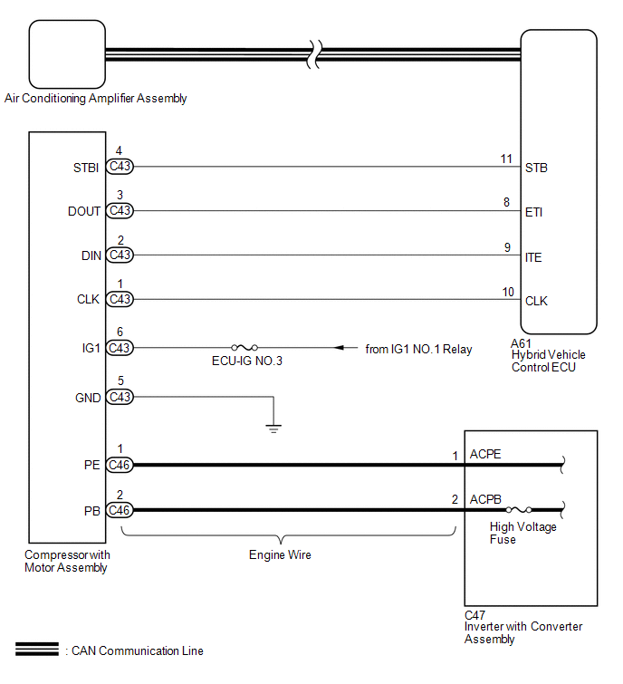
WIRING DIAGRAM
CAUTION / NOTICE / HINT
CAUTION:
- Wear insulated gloves and pull out the service plug grip before inspection as procedures may require disconnecting high-voltage connectors. Carry the removed service plug in your pocket to prevent other technicians from accidentally reconnecting it while you are servicing the vehicle.
- Do not touch the high-voltage connectors or terminals for 10 minutes after the service plug grip is removed.
NOTICE:
- Inspect the fuses for circuits related to this system before performing the following procedure.
-
After the power switch is turned off, there may be a waiting time before disconnecting the negative (-) auxiliary battery terminal.
Click here
.gif)
-
When disconnecting and reconnecting the auxiliary battery terminal
Click here
HINT:
When disconnecting and reconnecting the auxiliary battery, there is an automatic learning function that completes learning when the respective system is used.
Click here
- The hybrid control system and air conditioning system output DTCs separately. Perform troubleshooting for the hybrid control system first if DTCs from these systems are output simultaneously.
PROCEDURE
| 1. | CHECK CAN COMMUNICATION SYSTEM |
(a) Using the Techstream, check if the CAN communication system is functioning normally.
Click here
| Result | Proceed to |
|---|---|
| CAN communication system DTCs are not output | A |
| CAN communication system DTCs are output | B |
| B | .gif) | GO TO CAN COMMUNICATION SYSTEM |
|
.gif)
| 2. | CHECK FOR DTC (HYBRID CONTROL SYSTEM) |
(a) Check if hybrid control system DTCs are output.
Click here
OK:
Hybrid control system DTCs are not output.
| NG | | GO TO HYBRID CONTROL SYSTEM |
|
| 3. | INSPECT HIGH VOLTAGE FUSE |
CAUTION:
Be sure to wear insulated gloves.
(a) Turn the power switch off.
(b) Remove the service plug grip.
Click here
CAUTION:
Do not touch the high-voltage connectors or terminals for 10 minutes after the service plug grip is removed.
NOTICE:
After removing the service plug grip, turning the power switch on (READY) may cause a malfunction. Do not turn the power switch on (READY) with the service plug grip removed.
(c) Remove the connector cover assembly.
Click here
NOTICE:
Be sure to prevent foreign matter or water from entering the inverter with converter assembly.
| (d) Check that bolts A and B are tightened securely. |
|
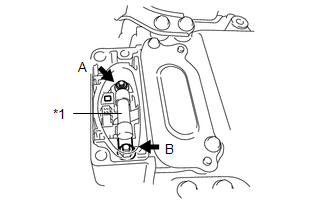
(e) Measure the resistance according to the value(s) in the table below.
Standard Resistance:
| Tester Item (Tester Connection) | Condition | Specified Condition |
|---|---|---|
| High voltage fuse (A - B) | Always | Below 1 Ω |
| NG | | REPLACE HIGH VOLTAGE FUSE |
|
| 4. | INSPECT ENGINE WIRE |
CAUTION:
Be sure to wear insulated gloves.
(a) Disconnect the C47 and C46 engine wire connectors.
Click here
NOTICE:
Do not allow any foreign matter or water to enter the compressor with motor assembly.
(b) Measure the resistance according to the value(s) in the table below.
Standard Resistance:
| Tester Connection | Condition | Specified Condition |
|---|---|---|
| C46-1 (PE) - C47-1 (ACPE) | Always | Below 1 Ω |
| C46-2 (PB) - C47-2 (ACPB) | Always | Below 1 Ω |
| C46-1 (PE) or C47-1 (ACPE) - Body ground | Always | 10 kΩ or higher |
| C46-2 (PB) or C47-2 (ACPB) - Body ground | Always | 10 kΩ or higher |
| OK | | REPLACE COMPRESSOR WITH MOTOR ASSEMBLY |
| NG | | REPLACE ENGINE WIRE |
READ NEXT:
 A/C Inverter High Voltage Output System Malfunction (B1472)
DESCRIPTION The inverter in the compressor with motor assembly outputs high-voltage to operate the motor. If there is an open or short in the output circuit, the hybrid vehicle control ECU will stop c
A/C Inverter Start-up Signal System Malfunction (B1473)
DESCRIPTION The inverter activation signal is sent to the compressor with motor assembly from the hybrid vehicle control ECU. Compressor control is stopped and this DTC is stored if there is an open o
A/C Inverter Malfunction (B1474)
DESCRIPTION DTC No. Detection Item DTC Detection Condition Trouble Area Memory Note B1474 A/C Inverter Malfunction A/C inverter malfunction
Compressor with motor assembly
C
SEE MORE:
Steering Angle Sensor Communication Error (C1784)
DESCRIPTION Steering sensor signals are sent to the absorber control ECU via CAN communication. When there is a communication malfunction, the malfunction will be detected by the diagnosis function. DTC No. Detection Item DTC Detection Condition Trouble Area Warning Indicate C1784 S
Purge Valve
ComponentsCOMPONENTS ILLUSTRATION *1 PURGE VSV *2 FUEL VAPOR FEED HOSE *3 NO. 2 FUEL VAPOR FEED HOSE - - RemovalREMOVAL PROCEDURE 1. REMOVE PURGE VSV (a) Disconnect the wire harness clamp and connector from the purge VSV. (b) Slide the 2 clamps and disconnect
