Lexus NX: Inspection
INSPECTION
PROCEDURE
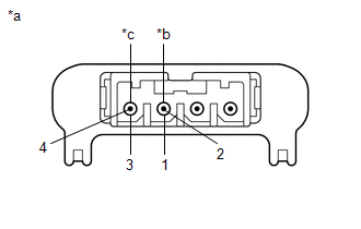
1. INSPECT NAVIGATION ANTENNA ASSEMBLY
| (a) Measure the resistance according to the value(s) in the table below. Standard Resistance:
If the result is not as specified, replace the navigation antenna assembly. |
|
2. INSPECT ANTENNA CORD SUB-ASSEMBLY
(a) Measure the resistance according to the value(s) in the table below.
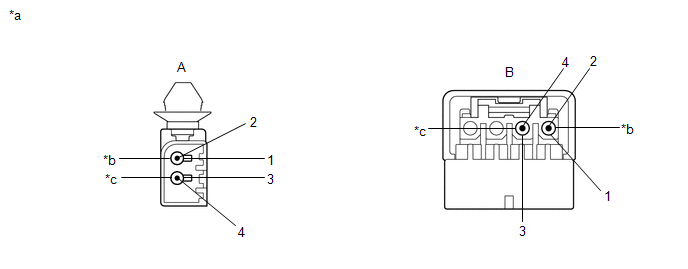
| *a | Component without harness connected (Antenna Cord Sub-assembly) | - | - |
| *c | Navigation Antenna | - | - |
Standard Resistance:
| Tester Connection | Condition | Specified Condition |
|---|---|---|
| A-1 - B-1 | Always | Below 1 Ω |
| A-2 - B-2 | Always | Below 1 Ω |
| A-3 - B-3 | Always | Below 1 Ω |
| A-4 - B-4 | Always | Below 1 Ω |
If the result is not as specified, replace the antenna cord sub-assembly.
READ NEXT:
 Installation
INSTALLATION PROCEDURE 1. INSTALL NAVIGATION ANTENNA ASSEMBLY 2. INSTALL NAVIGATION ANTENNA BRACKET (a) Attach the 4 guides to install the navigation antenna assembly as shown in the illustration.
Navigation Ecu
ComponentsCOMPONENTS ILLUSTRATION *1 NAVIGATION ECU *2 NO. 1 RADIO BRACKET *3 NO. 2 RADIO BRACKET *4 RADIO RECEIVER ASSEMBLY WITH BRACKET *5 NAVIGATION WIRE - - Remo
SEE MORE:
Oil Pressure Switch
ComponentsCOMPONENTS ILLUSTRATION *1 ENGINE OIL PRESSURE SWITCH ASSEMBLY - - N*m (kgf*cm, ft.*lbf): Specified torque TOYOTA Genuine Adhesive 1344, Three Bond 1344 or equivalent. ★ Precoated part - - RemovalREMOVAL PROCEDURE 1. REMOVE ENGINE OIL PRESSURE SWITCH
Inspection
INSPECTION PROCEDURE 1. INSPECT CLOCK ASSEMBLY (a) Check the illumination. Apply auxiliary battery voltage to the connector and check the illumination condition. OK: Measurement Condition Specified Condition Auxiliary battery positive (+) → Terminal 6 (ILL+) Auxiliary battery positive
