Lexus NX: Removal
REMOVAL
PROCEDURE
1. PRECAUTION
NOTICE:
After the power switch is turned off, there may be a waiting time before disconnecting the negative (-) auxiliary battery terminal.
Click here .gif)
2. REMOVE NO. 3 DECK BOARD SUB-ASSEMBLY
Click here
3. REMOVE REAR DECK FLOOR BOX
Click here
4. REMOVE DECK FLOOR BOX LH
Click here
5. DISCONNECT CABLE FROM NEGATIVE AUXILIARY BATTERY TERMINAL
Click here
6. REMOVE GLOVE COMPARTMENT DOOR ASSEMBLY
Click here
7. REMOVE NO. 2 INSTRUMENT PANEL UNDER COVER SUB-ASSEMBLY
Click here
8. REMOVE ECU INTEGRATION BOX RH
Click here
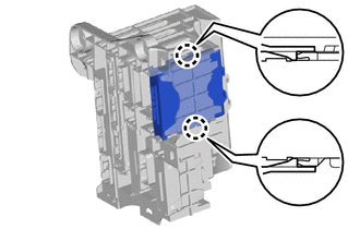
9. REMOVE CLEARANCE WARNING ECU ASSEMBLY
| (a) Detach the 2 claws and remove the clearance warning ECU assembly. |
|
READ NEXT:
 Installation
INSTALLATION PROCEDURE 1. INSTALL CLEARANCE WARNING ECU ASSEMBLY (a) Attach the 2 claws to install the clearance warning ECU assembly. 2. INSTALL ECU INTEGRATION BOX RH Click here 3. INSTALL NO. 2 I
Precaution
PRECAUTION PRECAUTION FOR SERVICING VEHICLE (a) After ECUs or parts are removed and installed, or replaced during inspection or servicing the vehicle, it is necessary to perform certain procedures (ad
SEE MORE:
Diagnosis System
DIAGNOSIS SYSTEM DESCRIPTION (a) The DCM (telematics transceiver) control the vehicle safety connect system functions. Safety connect system data and Diagnostic Trouble Codes (DTCs) can be read through the vehicle Data Link Connector 3 (DLC3). In some cases, a malfunction may be occurring in the saf
Data List / Active Test
DATA LIST / ACTIVE TEST NOTICE: In the table below, the values listed under "Normal Condition" are reference values. Do not depend solely on these reference values when deciding whether a part is faulty or not. DATA LIST HINT:
Using the Techstream to read the Data List allows the values or states
© 2016-2026 Copyright www.lexunx.com
