Lexus NX: Removal
REMOVAL
CAUTION / NOTICE / HINT
HINT:
- Use the same procedure for the RH and LH sides.
- The procedure listed below is for the LH side.
PROCEDURE
1. PRECAUTION
Click here .gif)
2. REMOVE FRONT DOOR TRIM COVER LH
Click here
3. REMOVE FRONT DOOR INSIDE HANDLE BEZEL PLUG LH
Click here
4. REMOVE POWER WINDOW REGULATOR MASTER SWITCH ASSEMBLY WITH FRONT DOOR ARMREST BASE PANEL
Click here
5. REMOVE FRONT DOOR TRIM BOARD SUB-ASSEMBLY LH
Click here
6. REMOVE OUTER MIRROR INSTALL HOLE COVER LH
Click here
7. REMOVE OUTER REAR VIEW MIRROR ASSEMBLY LH
Click here
8. REMOVE OUTER MIRROR LH
Click here
9. REMOVE OUTER MIRROR COVER LH
Click here
10. REMOVE OUTER MIRROR BEZEL LH
Click here
11. REMOVE LOWER OUTER MIRROR COVER LH
Click here
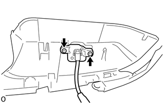
12. REMOVE SIDE TELEVISION CAMERA ASSEMBLY LH
| (a) Remove the 2 screws and side television camera assembly LH. |
|
READ NEXT:
 Installation
INSTALLATION CAUTION / NOTICE / HINT HINT:
Use the same procedure for the RH and LH sides.
The procedure listed below is for the LH side.
PROCEDURE 1. INSTALL SIDE TELEVISION CAMERA ASSEMBLY L
Components
COMPONENTS ILLUSTRATION *A except Sport Package - - *1 FRONT CENTER ULTRASONIC SENSOR *2 FRONT CORNER ULTRASONIC SENSOR *3 FRONT CORNER ULTRASONIC SENSOR RETAINER *4 NO.
SEE MORE:
Check Mode Procedure
CHECK MODE PROCEDURE REFRIGERANT GAS VOLUME CHECK IN NORMAL OPERATION (CHECK A/C SWITCH INDICATOR AND DTC) *a Example (a) Turn the power switch on (READY). (b) Check that A/C switch indicator remains on when the following conditions are met. Measurement Condition Item Condition A/C
Lost Communication with Instrument Panel Cluster Control Module (Combination Meter) (U0155)
DESCRIPTION The ECM and combination meter assembly send and receiver signals via CAN communication. If a communication error occurs between the ECM and combination meter assembly, the ECM illuminates the MIL and stores this DTC. DTC No. Detection Item DTC Detection Condition Trouble Area
© 2016-2026 Copyright www.lexunx.com
