Lexus NX: Removal
REMOVAL
PROCEDURE
1. REMOVE CONSOLE ARMREST ASSEMBLY
Click here .gif)
2. REMOVE REAR UPPER CONSOLE PANEL
Click here
3. REMOVE UPPER NO. 2 CONSOLE PANEL GARNISH
Click here
4. REMOVE UPPER NO. 1 CONSOLE PANEL GARNISH
Click here
5. REMOVE INSTRUMENT SIDE PANEL LH
Click here
6. REMOVE NO. 1 INSTRUMENT PANEL SAFETY PAD SUB-ASSEMBLY
Click here
7. REMOVE NO. 1 INSTRUMENT PANEL UNDER COVER SUB-ASSEMBLY
Click here
8. REMOVE LOWER NO. 1 INSTRUMENT PANEL FINISH PANEL
Click here
9. REMOVE NO. 1 SWITCH HOLE BASE
Click here
10. REMOVE INSTRUMENT SIDE PANEL RH
Click here
11. REMOVE NO. 2 INSTRUMENT PANEL SAFETY PAD SUB-ASSEMBLY
Click here
12. REMOVE CENTER INSTRUMENT CLUSTER FINISH PANEL ASSEMBLY
Click here
13. REMOVE SHIFT LEVER KNOB SUB-ASSEMBLY
Click here
14. REMOVE REAR UPPER CONSOLE PANEL SUB-ASSEMBLY
Click here
15. REMOVE SHIFT POSITION INDICATOR
Click here
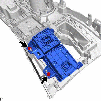
16. REMOVE INTEGRATION CONTROL AND PANEL ASSEMBLY (BRAKE HOLD SWITCH)
| (a) Remove the 2 screws and integration control and panel assembly (brake hold switch) from the upper rear console panel sub-assembly. |
|
READ NEXT:
 Inspection
INSPECTION PROCEDURE 1. INSPECT INTEGRATION CONTROL AND PANEL ASSEMBLY (BRAKE HOLD SWITCH) (a) Measure the resistance according to the value(s) in the table below. Standard Resistance: Tester C
Installation
INSTALLATION PROCEDURE 1. INSTALL INTEGRATION CONTROL AND PANEL ASSEMBLY (BRAKE HOLD SWITCH) (a) Install the integration control and panel assembly (brake hold switch) to the upper rear console pan
SEE MORE:
Inspection
INSPECTION PROCEDURE 1. INSPECT GLOVE BOX LIGHT ASSEMBLY (a) Apply battery voltage to the connector and check the light illumination condition. OK: Measurement Condition Specified Condition Battery positive (+) → 2 (B) Battery negative (-) → 1 (L) Illuminates If the result is n
Accelerator Pedal Sensor
ComponentsCOMPONENTS ILLUSTRATION *1 ACCELERATOR PEDAL SENSOR ASSEMBLY *2 ACCELERATOR PEDAL SENSOR CONNECTOR N*m (kgf*cm, ft.*lbf): Specified torque - - On-vehicle InspectionON-VEHICLE INSPECTION PROCEDURE 1. INSPECT ACCELERATOR PEDAL SENSOR ASSEMBLY (a) Connect the Techstr
