Lexus NX: Removal
REMOVAL
PROCEDURE
1. PRECAUTION
CAUTION:
Be sure to read Precoution thoroughly before serving.
Click here .gif)
NOTICE:
After turning the power switch off, there may be a waiting time before disconnecting the negative (-) auxiliary battery terminal.
Click here
2. DISABLE BRAKE CONTROL
(a) Wait for at least 2 minutes after turning the power switch off.
NOTICE:
When the brake pedal is depressed or the door courtesy switch is turned on even if the power switch is off, the brake control system activates. Therefore, do not depress the brake pedal or open/close the doors until the reservoir level switch connector is disconnected.
| (b) Disconnect the reservoir level switch connector with the parking brake applied. |
|
.png)
(c) Loosen the nut and disconnect the negative (-) auxiliary battery terminal.
(d) Depress the brake pedal 40 times or more to return all the fluid in the accumulator back to the reservoir.
(e) Check that the brake pedal cannot be further depressed.
3. REMOVE WINDSHIELD WIPER MOTOR AND LINK ASSEMBLY
Click here
4. REMOVE SUSPENSION TOWER DAMPER
-
w/ Damper:
Click here
-
w/o Damper:
Click here
5. REMOVE OUTER COWL TOP PANEL
Click here
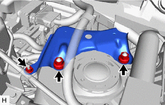
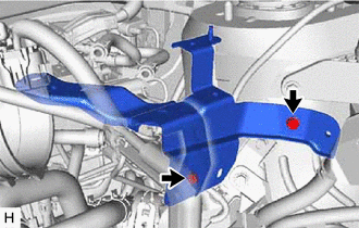
6. REMOVE COWL BODY MOUNTING REINFORCEMENT LH
| (a) Remove the 3 nuts and cowl body mounting reinforcement LH. |
|
7. REMOVE AIR CLEANER CASE SUB-ASSEMBLY
Click here
8. DRAIN BRAKE FLUID
NOTICE:
Wash off brake fluid immediately if it comes in contact with any painted surface.
9. REMOVE NO. 1 INSTRUMENT PANEL UNDER COVER SUB-ASSEMBLY
Click here
10. REMOVE PUSH ROD PIN
Click here
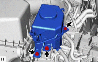
11. DISCONNECT BRAKE MASTER CYLINDER RESERVOIR ASSEMBLY
| (a) Remove the 3 bolts and disconnect the brake master cylinder reservoir with reservoir bracket. |
|
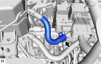
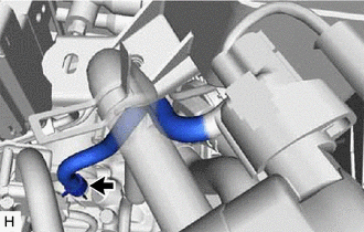
12. DISCONNECT NO. 2 RESERVOIR HOSE
| (a) Slide the clip and disconnect the No. 2 reservoir hose from the brake booster with master cylinder assembly. |
|
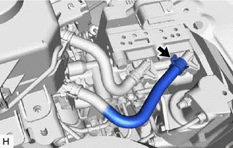
13. DISCONNECT NO. 1 RESERVOIR HOSE
| (a) Slide the clip and disconnect the No. 1 reservoir hose from the brake booster with master cylinder assembly. |
|
14. DISCONNECT BRAKE ACTUATOR HOSE
| (a) Slide the clip and disconnect the brake actuator hose from the brake booster pump assembly. |
|
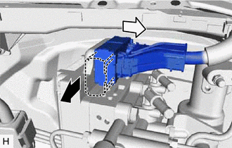
15. REMOVE BRAKE MASTER CYLINDER RESERVOIR ASSEMBLY
16. REMOVE RESERVOIR BRACKET
| (a) Remove the 2 bolts and reservoir bracket. |
|
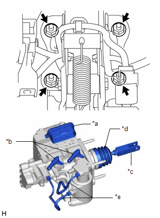
17. REMOVE BRAKE BOOSTER WITH MASTER CYLINDER ASSEMBLY
(a) Release the lock lever and disconnect the connector from the brake booster with master cylinder assembly.
.png) | Release the lock lever |
.png) | Disconnect the connector |
NOTICE:
Be careful not to allow the brake fluid to enter the removed connector.
| (b) Remove the 2 bolts and No. 2 brake tube clamp bracket from the brake booster with master cylinder assembly. |
|
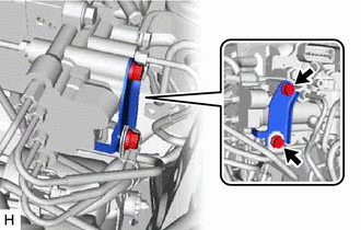
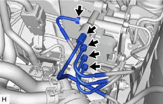
| (c) Using a union nut wrench, disconnect the 5 brake tubes from the brake booster with master cylinder assembly. |
|
| (d) Remove the 4 nuts and brake booster with master cylinder assembly. NOTICE:
|
|
18. REMOVE BRAKE BOOSTER GASKET
READ NEXT:
 Installation
INSTALLATION PROCEDURE 1. INSTALL BRAKE BOOSTER GASKET (a) Install a new brake booster gasket to the brake booster with master cylinder assembly. 2. INSTALL BRAKE BOOSTER WITH MASTER CYLINDER ASSEMBLY
Components
COMPONENTS ILLUSTRATION *1 DECK FLOOR BOX LH *2 NO. 3 DECK BOARD SUB-ASSEMBLY *3 REAR DECK FLOOR BOX *4 NEGATIVE AUXILIARY BATTERY TERMINAL N*m (kgf*cm, ft.*lbf): Specified
SEE MORE:
Installation
INSTALLATION CAUTION / NOTICE / HINT HINT: Perform "Inspection After Repair" after replacing the EGR valve assembly. Click here PROCEDURE 1. INSTALL EGR VALVE ASSEMBLY HINT: Perform "Inspection After Repair" after replacing the EGR valve assembly. Click here (a) Install 2 new gaskets to the N
Inspection
INSPECTION PROCEDURE 1. INSPECT AIR CONDITIONING CONTROL ASSEMBLY (SEAT BELT WARNING LIGHT) (for Rear Side) (a) Check the seat belt warning light illumination. OK: Measurement Condition Specified Condition Battery positive (+) → Terminal 8 (IG+) Battery negative (-) → 1 (RRID) RH
