Lexus NX: Installation
INSTALLATION
PROCEDURE
1. INSTALL BRAKE BOOSTER GASKET
(a) Install a new brake booster gasket to the brake booster with master cylinder assembly.
2. INSTALL BRAKE BOOSTER WITH MASTER CYLINDER ASSEMBLY
| (a) Install the brake booster with master cylinder assembly with the 4 nuts. Torque: 12.7 N·m {130 kgf·cm, 9 ft·lbf} NOTICE:
|
|
.png)
| (b) Using a union nut wrench, tighten each brake line. Torque: Specified tightening torque : 15.2 N·m {155 kgf·cm, 11 ft·lbf} NOTICE: Do not kink or damage the brake tubes. HINT:
|
|
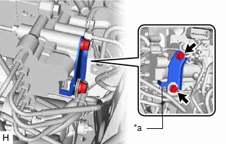
| (c) Install the No. 2 brake tube clamp bracket to the brake booster with master cylinder assembly with the 2 bolts. Torque: 5.0 N·m {51 kgf·cm, 44 in·lbf} NOTICE: Securely install the No. 2 brake tube clamp bracket so that its stopper contacts the brake booster with master cylinder assembly as shown in the illustration. |
|
(d) Connect the connector to the brake booster with master cylinder assembly.
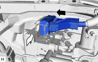
.png) | Connect the connector |
.png) | Lock the lock lever |
NOTICE:
- Make sure that the connector can be connected smoothly. Do not allow water, oil or dirt to enter.
- Make sure that the connector lock is locked securely.
3. INSTALL RESERVOIR BRACKET
(a) Install the reservoir bracket with the 2 bolts.
Torque:
8.5 N·m {87 kgf·cm, 75 in·lbf}
4. CONNECT BRAKE ACTUATOR HOSE
(a) Connect the brake actuator hose to the brake booster pump assembly, and slide the clamp to secure it.
| | Vehicle Interior |
NOTICE:
- Make sure to match the identification mark (green) on the hose with the brake booster pump rib.
- Make sure to install the hose to the proper location.
- Install the clip within the range shown in the illustration.
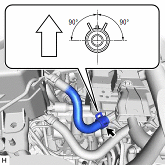
5. CONNECT NO. 1 RESERVOIR HOSE
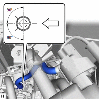
(a) Connect the No. 1 reservoir hose to the brake booster with master cylinder assembly, and slide the clip to secure it.
| | Up |
NOTICE:
- Make sure to match the identification mark (white (unpainted color)) on the hose and brake booster with master cylinder assembly.
- When connecting the No. 1 reservoir hose, face the identification mark up.
- Make sure to install the hose to the proper location.
- Install the clip within the range shown in the illustration.
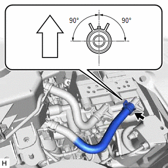
6. CONNECT NO. 2 RESERVOIR HOSE
(a) Connect the No. 2 reservoir hose to the brake booster with master cylinder assembly, and slide the clip to secure it.
| | Up |
NOTICE:
- Make sure to match the identification mark (green) on the No. 2 reservoir hose and brake booster with master cylinder assembly.
- When connecting the No. 2 reservoir hose, face the identification mark up.
- Make sure to install the hose to the proper location.
- Install the clip within the range shown in the illustration.
7. INSTALL BRAKE MASTER CYLINDER RESERVOIR ASSEMBLY
(a) Install the brake master cylinder reservoir with bracket with the 3 bolts.
Torque:
8.5 N·m {87 kgf·cm, 75 in·lbf}
8. INSTALL PUSH ROD PIN
Click here .gif)
9. INSTALL AIR CLEANER CASE SUB-ASSEMBLY
Click here
10. FILL RESERVOIR WITH BRAKE FLUID
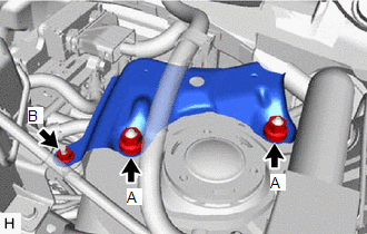
11. INSTALL COWL BODY MOUNTING REINFORCEMENT LH
| (a) Install the cowl body mounting reinforcement LH with the 3 nuts. Torque: Nut A : 50 N·m {510 kgf·cm, 37 ft·lbf} Nut B : 8.5 N·m {87 kgf·cm, 75 in·lbf} |
|
12. INSTALL OUTER COWL TOP PANEL
Click here
13. INSTALL SUSPENSION TOWER DAMPER
-
w/ Damper:
Click here
-
w/o Damper:
Click here
14. INSTALL WINDSHIELD WIPER MOTOR AND LINK ASSEMBLY
Click here
15. CONNECT CABLE TO NEGATIVE AUXILIARY BATTERY TERMINAL
(a) Connect the reservoir level switch connector.
(b) Connect the negative (-) auxiliary battery terminal and tighten the nut.
Torque:
5.4 N·m {55 kgf·cm, 48 in·lbf}
16. INITIALIZATION AFTER RECONECTING AUXILIARY BATTERY TERMINAL
Click here
HINT:
When disconnecting and reconnecting the auxiliary battery, there is an automatic learning function that completes learning when the respective system is used.
Click here
17. BLEED BRAKE SYSTEM
Click here
18. INSPECT AND ADJUST BRAKE PEDAL
Click here
19. OBTAIN ZERO POINT OF YAW RATE AND ACCELERATION SENSOR
HINT:
After the brake booster with master cylinder assembly is replaced, obtain the zero point of the yaw rate and acceleration sensor.
Click here
20. INSTALL NO. 1 INSTRUMENT PANEL UNDER COVER SUB-ASSEMBLY
Click here
READ NEXT:
 Components
COMPONENTS ILLUSTRATION *1 DECK FLOOR BOX LH *2 NO. 3 DECK BOARD SUB-ASSEMBLY *3 REAR DECK FLOOR BOX *4 NEGATIVE AUXILIARY BATTERY TERMINAL N*m (kgf*cm, ft.*lbf): Specified
Removal
REMOVAL CAUTION / NOTICE / HINT NOTICE: While the auxiliary battery is connected, even if the power switch is off, the brake control system activates when the brake pedal is depressed or any door cour
SEE MORE:
Brake Warning Light does not Come ON
DESCRIPTION The skid control ECU (brake booster with master cylinder assembly) is connected to the combination meter assembly via CAN communication. CAUTION / NOTICE / HINT NOTICE: When replacing the skid control ECU (brake booster with master cylinder assembly), perform initialization and calibrati
Adjustment
ADJUSTMENT PROCEDURE 1. INSPECT SHIFT LEVER POSITION (a) While moving the shift lever from N to each position, check that the lever moves smoothly and that the shift position indicator comes on properly according to the shift lever position. (b) Put the vehicle into the READY-on state and check the
