Lexus NX: Removal
REMOVAL
CAUTION / NOTICE / HINT
HINT:
- Use the same procedure for the RH and LH sides.
- The procedure listed below is for the LH side.
PROCEDURE
1. REMOVE REAR WHEEL
Click here .gif)
2. REMOVE TAIL EXHAUST PIPE ASSEMBLY
Click here
3. REMOVE REAR AXLE SHAFT NUT LH
Click here
4. REMOVE REAR SUSPENSION BRACE SUB-ASSEMBLY
Click here
5. REMOVE REAR SUSPENSION ARM COVER LH
Click here
6. REMOVE REAR DRIVE SHAFT ASSEMBLY LH
| (a) Put matchmarks on the rear drive shaft assembly LH and rear axle hub and bearing assembly. |
|
| (b) Put matchmarks on the rear drive shaft assembly LH and differential side gear shaft sub-assembly. |
|
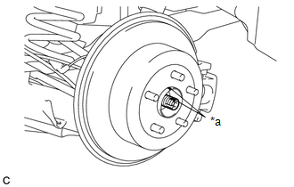
(c) Using a screwdriver or an equivalent, hold the differential side gear shaft sub-assembly as shown in the illustration.
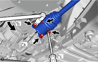
(d) Remove the 4 nuts and 4 washers.
(e) Push the rear drive shaft inboard joint assembly LH toward the outside of the vehicle and disconnect the rear drive shaft assembly LH from the differential side gear shaft sub-assembly.
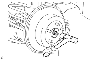
| (f) Using a plastic-faced hammer, remove the rear drive shaft assembly LH from the rear axle hub and bearing assembly. NOTICE:
If it is difficult to remove, tap the end of the rear drive shaft assembly LH using a brass bar and a hammer. |
|
READ NEXT:
 Disassembly
DISASSEMBLY CAUTION / NOTICE / HINT NOTICE:
When using a vise, place aluminum plates between the part and vise.
When using a vise, do not overtighten it.
HINT:
Use the same procedure for th
Inspection
INSPECTION CAUTION / NOTICE / HINT NOTICE:
When using a vise, place aluminum plates between the part and vise.
When using a vise, do not overtighten it.
PROCEDURE 1. INSPECT REAR DRIVE SHAFT A
Reassembly
REASSEMBLY CAUTION / NOTICE / HINT NOTICE:
When using a vise, place aluminum plates between the part and vise.
When using a vise, do not overtighten it.
HINT:
Use the same procedure for the
SEE MORE:
Components
COMPONENTS ILLUSTRATION *A w/ AVS - - *1 REAR SPEED SENSOR LH - - N*m (kgf*cm, ft.*lbf): Specified torque - - ILLUSTRATION *A w/o AVS - - *1 REAR SPEED SENSOR LH - - N*m (kgf*cm, ft.*lbf): Specified torque - -
Inspection
INSPECTION PROCEDURE 1. INSPECT TILT AND TELESCOPIC SWITCH (a) Measure the resistance according to the value(s) in the table below. Standard Resistance: Tester Connection Switch Condition Specified Condition 1 (VC) - 3 (MSW) Tilt up 342 to 378 Ω Tilt down 1890.5 to 2089.5 Î
