Lexus NX: Removal
REMOVAL
PROCEDURE
1. REMOVE NO. 1 ENGINE UNDER COVER ASSEMBLY
Click here .gif)
2. DRAIN COOLANT (for Inverter Coolant)
Click here
3. REMOVE NO. 2 MOTOR WATER JACKET COVER ASSEMBLY
| (a) Remove the 5 bolts. |
|
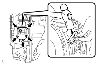
(b) Insert the blade of an oil pan seal cutter between the transaxle housing. Cut through the applied sealer and remove the No. 2 motor water jacket cover assembly.
NOTICE:
Be careful not to damage the contact surfaces of the transaxle housing where the No. 2 motor water jacket cover assembly is installed.
4. REMOVE HYBRID VEHICLE TRANSAXLE ASSEMBLY
Click here
5. REMOVE FRONT ENGINE MOUNTING BRACKET
Click here
6. REMOVE NO. 1 TRANSMISSION CONTROL CABLE BRACKET
Click here
7. REMOVE OIL COOLER TUBE CLAMP
Click here
8. REMOVE NO. 2 AUTOMATIC TRANSMISSION CASE COVER
Click here
9. REMOVE NO. 1 MOTOR WATER JACKET COVER ASSEMBLY
| (a) Remove the 8 bolts. |
|
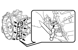
(b) Insert the blade of an oil pan seal cutter between the transaxle housing. Cut through the applied sealer and remove the No. 1 motor water jacket cover assembly.
NOTICE:
Be careful not to damage the contact surfaces of the transaxle housing where the No. 1 motor water jacket cover assembly is installed.
10. REMOVE NO. 3 MOTOR WATER JACKET COVER ASSEMBLY
| (a) Remove the 12 bolts. |
|
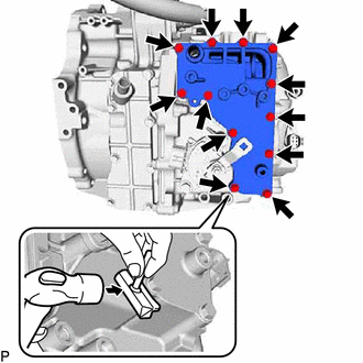
(b) Insert the blade of an oil pan seal cutter between the transaxle housing. Cut through the applied sealer and remove the No. 3 motor water jacket cover assembly.
NOTICE:
Be careful not to damage the contact surfaces of the transaxle housing where the No. 3 motor water jacket cover assembly is installed.
READ NEXT:
 Installation
INSTALLATION PROCEDURE 1. INSTALL NO. 3 MOTOR WATER JACKET COVER ASSEMBLY (a) Remove any remaining seal packing from the transaxle housing installation surface and bolt holes. NOTICE:
Clean and deg
Components
COMPONENTS ILLUSTRATION *1 NO. 1 ENGINE UNDER COVER ASSEMBLY - - ILLUSTRATION *1 INVERTER BRACKET ASSEMBLY *2 INVERTER WATER PUMP WITH MOTOR ASSEMBLY *3 NO. 5 INVERTER COO
SEE MORE:
ICS Detection Area Adjustment Incomplete (C1AF0)
DESCRIPTION When ICS detection area adjustment is incomplete, the clearance warning ECU assembly stores DTC C1AF0. DTC No. Detection Item DTC Detection Condition Trouble Area C1AF0 ICS Detection Area Adjustment Incomplete ICS detection area adjustment incomplete
Intelligent cle
Driver Side Door Entry Lock and Unlock Functions do not Operate
DESCRIPTION If the entry lock and unlock functions do not operate for the driver door only, the request code may not be being transmitted from the driver door or the front door outside handle assembly (for driver door) (touch sensor) may be malfunctioning. If the entry functions for other doors oper
