- DTC judgment completed
- System normal
Lexus NX: EVAP System Tank Vapor Line Restricted/Blocked (P00FE)
Lexus NX Service Manual / Engine & Hybrid System / 2ar-fxe (engine Control) / Sfi System / EVAP System Tank Vapor Line Restricted/Blocked (P00FE)
DTC SUMMARY
| DTC No. | Detection Item | DTC Detection Condition | Trouble Area | MIL | Memory |
|---|---|---|---|---|---|
| P00FE | EVAP System Tank Vapor Line Restricted/Blocked | Leak detection pump creates negative pressure (vacuum) in EVAP system and EVAP system pressure is measured. When the fuel level in the fuel tank is 85% or less and the leak detection pump is operating, the EVAP system pressure decreases quickly. |
| Comes on | DTC stored |
| DTC No. | Monitoring Item | Detection Timing | Detection Logic |
|---|---|---|---|
| P00FE | EVAP vent line blocked | EVAP monitoring (power switch off) | 2 trip |
DESCRIPTION
The description can be found in EVAP (Evaporative Emission) System.
Click here .gif)
MONITOR DESCRIPTION
5 hours* after the power switch is turned off, the leak detection pump creates negative pressure (vacuum) in the EVAP (Evaporative Emission) system. The ECM monitors for leaks and actuator malfunctions based on the EVAP pressure.
HINT:
*: If the engine coolant temperature is not less than 35°C (95°F) 5 hours after the power switch is turned off, the monitor check starts 2 hours later. If it is still not less than 35°C (95°F) 7 hours after the power switch is turned off, the monitor check starts 2.5 hours later.
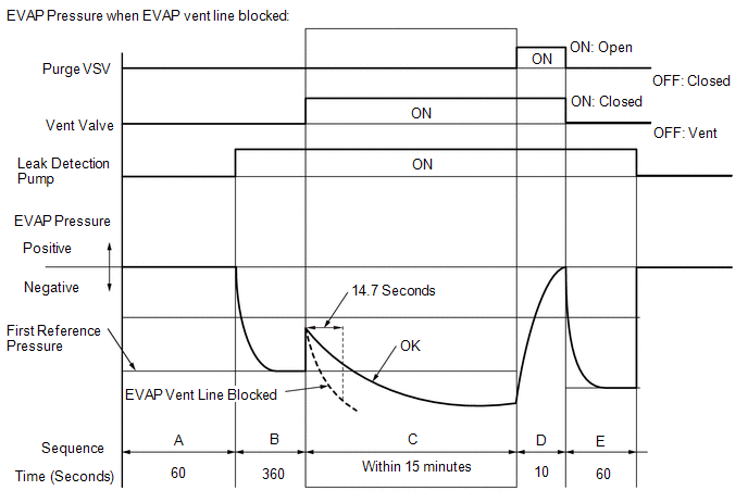
| Sequence | Operation | Description | Duration |
|---|---|---|---|
| - | ECM activation | Activated by soak timer 5, 7 or 9.5 hours after power switch turned off. | - |
| A | Atmospheric pressure measurement | Vent valve is turned off (vent) and EVAP system pressure is measured by ECM in order to register atmospheric pressure. If pressure in EVAP system is not between 70 to 110 kPa(abs) [10.15 to 15.95 psi(abs)], ECM cancels EVAP system monitor. | 60 seconds |
| B | First reference pressure measurement | In order to determine reference pressure, leak detection pump creates negative pressure (vacuum) through reference orifice and then ECM checks if leak detection pump and vent valve operate normally. | 360 seconds |
| C | EVAP system pressure measurement | Vent valve is turned on (closed) to shut EVAP system. Negative pressure (vacuum) is created in EVAP system, and EVAP system pressure is then measured. Write down measured value as it will be used in leak check. If EVAP pressure does not stabilize within 15 minutes, ECM cancels EVAP system monitor. | 15 minutes* |
| D | Purge VSV monitor | Purge VSV is opened and then EVAP system pressure is measured by ECM. Large increase indicates normal. | 10 seconds |
| E | Second reference pressure measurement | After second reference pressure measurement, leak check is performed by comparing first and second reference pressure measurements. If stabilized system pressure is higher than second reference pressure, ECM determines that EVAP system is leaking. | 60 seconds |
| - | Final check | Atmospheric pressure is measured and then monitoring result is recorded by ECM. | - |
*: If only a small amount of fuel is in the fuel tank, it takes longer for the EVAP pressure to stabilize.
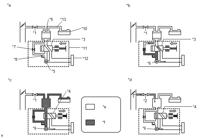
| *1 | Purge VSV: Off (Closed) | *2 | Purge VSV: On (Open) |
| *3 | Vent Valve: Off (Vent) | *4 | Vent Valve: On (Closed) |
| *5 | Leak Detection Pump: Off | *6 | Leak Detection Pump: On |
| *7 | Reference Orifice (0.02 inch) | *8 | Canister Pressure Sensor |
| *9 | Canister | *10 | Fuel Tank |
| *11 | Canister Pump Module | *12 | Canister Filter |
| *13 | Fuel Tank Vent Hose | - | - |
| *a | Operation A: Atmospheric Pressure Measurement | *b | Operation B, E: Reference Pressure Measurement |
| *c | Operation C: EVAP System Pressure Measurement | *d | Operation D: Purge VSV Monitor |
| *e | Atmospheric Pressure | *f | Negative Pressure |
-
(a) P00FE: EVAP vent line blocked
During operation C, if the EVAP system pressure is below the threshold after 14.7 seconds, the ECM will determine that there is blockage between the fuel tank and canister, illuminate the MIL and store this DTC (2 trip detection logic).
MONITOR STRATEGY
| Required Sensors/Components (Main) | Purge VSV Canister pump module |
| Required Sensors/Components (Related) | Fuel level sensor |
| Frequency of Operation | Once per driving cycle |
| Duration | Less than 7 minutes |
| MIL Operation | 2 driving cycles |
| Sequence of Operation | None |
TYPICAL ENABLING CONDITIONS
| Monitor runs whenever the following DTCs are not stored | None |
| Atmospheric pressure | 70 kPa(abs) [525 mmHg(abs)] or higher, and less than 111 kPa(abs) [836 mmHg(abs)] |
| Auxiliary battery voltage | 10.5 V or higher |
| Vehicle speed | Less than 4 km/h (2.5 mph) |
| Power switch | Off |
| Time after key-off | 5, 7 or 9.5 hours |
| Canister pressure sensor malfunction (P0452, P0453) | Not detected |
| Purge VSV | Not operated by scan tool |
| Vent valve | Not operated by scan tool |
| Leak detection pump | Not operated by scan tool |
| Both of the following conditions met before-key off | Conditions 1 and 2 |
| 1. Duration that vehicle is driven | 5 minutes or more |
| 2. EVAP purge operation | Performed |
| Engine coolant temperature | 4.4°C (40°F) or higher, and less than 35°C (95°F) |
| Intake air temperature | 4.4°C (40°F) or higher, and less than 35°C (95°F) |
| Fuel level (The ratio of fuel tank capacity) | 85% or less |
| Fuel level sensor malfunction (P0461, P0462, P0463) | Not detected |
| Lost communication with instrument panel cluster control module (U0155) | Not detected |
TYPICAL MALFUNCTION THRESHOLDS
| Judgment time after reached first 0.020 inch reference pressure (vary with first reference pressure) | 14.7 seconds |
| EVAP pressure (vary with first reference pressure, atmospheric pressure and engine coolant temperature) | Less than -2.5 kPa(gauge) [-0.363 psi(gauge)] |
CONFIRMATION DRIVING PATTERN
NOTICE:
- The Evaporative System Check (Automatic Mode) consists of 6 steps performed automatically by the Techstream. It takes a maximum of approximately 24 minutes.
- Do not perform the Evaporative System Check when the fuel tank is higher than 85% full because the cut-off valve may be closed, making the fuel tank leak check unavailable.
- Do not run the engine during this operation.
- When the temperature of the fuel is 35°C (95°F) or higher, a large amount of vapor forms and any check results become inaccurate. When performing the Evaporative System Check, keep the fuel temperature less than 35°C (95°F).
HINT:
-
After repair has been completed, clear the DTC and then check that the vehicle has returned to normal by performing the following All Readiness check procedure.
Click here
-
When clearing the permanent DTCs, refer to the "CLEAR PERMANENT DTC" procedure.
Click here
- Connect the Techstream to the DLC3.
- Turn the power switch on (IG).
- Turn the Techstream on.
- Clear the DTCs (even if no DTCs are stored, perform the clear DTC procedure).
- Turn the power switch off and wait for at least 30 seconds.
- Turn the power switch on (IG).
- Turn the Techstream on.
- Enter the following menus: Powertrain / Engine and ECT / Utility / Evaporative System Check / Automatic Mode.
- After the Evaporative System Check is completed, check for All Readiness by entering the following menus: Powertrain / Engine / Utility / All Readiness.
- Input the DTC: P00FE.
-
Check the DTC judgment result.
Techstream Display
Description
NORMAL
ABNORMAL
- DTC judgment completed
- System abnormal
INCOMPLETE
- DTC judgment not completed
- Perform driving pattern after confirming DTC enabling conditions
N/A
- Unable to perform DTC judgment
- Number of DTCs which do not fulfill DTC preconditions has reached ECU memory limit
HINT:
- If the judgment result is NORMAL, the system is normal.
- If the judgment result is ABNORMAL, the system is malfunctioning.
-
If the judgment result is INCOMPLETE or N/A and no pending DTC is output, perform a universal trip and check for permanent DTCs.
Click here
HINT:
- If a permanent DTC is output, the system is malfunctioning.
- If no permanent DTC is output, the system is normal.
PROCEDURE
| 1. | GO TO EVAP SYSTEM |
(a) Refer to EVAP System.
Click here
| NEXT | .gif) | END |
READ NEXT:
 Mass Air Flow Circuit Range / Performance Problem (P0101)
DESCRIPTION Refer to DTC P0102. Click here DTC No. Detection Item DTC Detection Condition Trouble Area MIL Memory P0101 Mass Air Flow Circuit Range / Performance Problem All of
Mass Air Flow Circuit Low (P0102,P0103)
DESCRIPTION The mass air flow meter sub-assembly is a sensor that measures the amount of air flowing through the throttle valve. The ECM uses this information to determine the fuel injection duration
Manifold Absolute Pressure Circuit Problem (P0106)
DESCRIPTION The manifold absolute pressure sensor detects pressure inside the intake manifold as an absolute pressure with a built-in sensor and outputs it as voltage. Based on the voltage from the m
SEE MORE:
Right Headlight ECU Malfunction (B242C,B242D)
DESCRIPTION These DTCs are output when an internal malfunction in the headlight ECU sub-assembly occurs. The headlight ECU sub-assembly LH outputs DTC B242C and B242D. DTC No. Detection Item DTC Detection Condition Trouble Area B242C Right Headlight ECU Malfunction Headlight ECU sub
Problem Symptoms Table
PROBLEM SYMPTOMS TABLE NOTICE: If the auxiliary battery voltage becomes low, windshield deicer operation is canceled to prioritize supplying power to the power steering system. for Power Tilt and Power Telescopic Steering Column: Click here for Manual Tilt and Manual Telescopic Steering Column: Cl
© 2016-2026 Copyright www.lexunx.com
